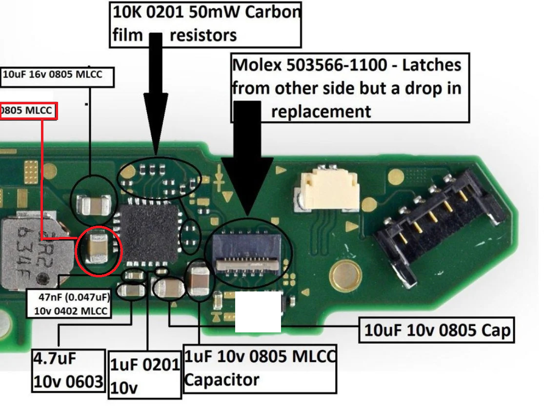
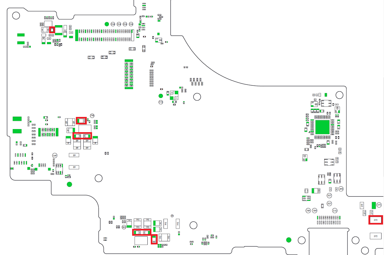
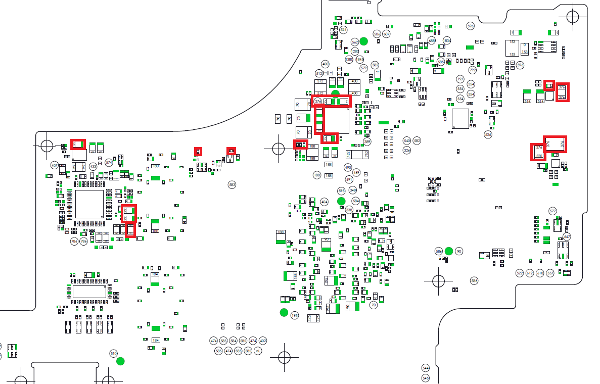
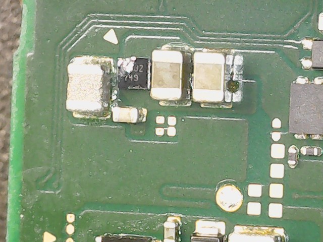
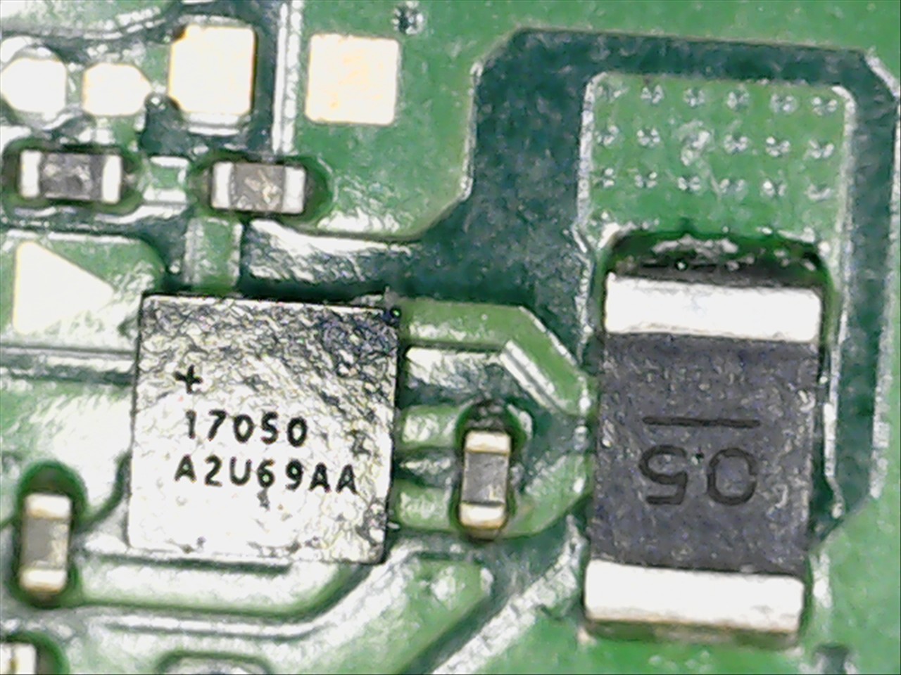
I have a dead Nintendo Switch. It won’t charge or show any signs of life. There is power coming from the USB-C into the circuit. I found a shorted capacitor (see picture link - remove spaces, red circle) next to the bq24193 chip. I removed the capacitor and the bq24193 chip but the short is still there. Any thoughts of what might be causing the short?
This is amazing thank you! Its also encouraging because it seems I was on the right path. So do I check all these spots then start pulling off IC’s to figure out which one is sending the short?
Indeed, though a bit of history or pics of the board might be helpful.
For example, liquid damaged boards have IC’s that fail more often than others (due to ingress paths) , in my experience a lot of the BGA style packages on this rail don’t even require replacement but just remove, scrub, wick and reball
They can often be troubshot with diode/resistance measurements relative to ground prior to removal
Thanks for asking. I took these IC’s off then put them back on as well as two IC’s on side A. Once I did that my short went away but now it won’t turn on. When I plug it in without the battery I get a steady .10amps
Can you confirm if you wicked the board and reballed these IC’s with stencil and paste?
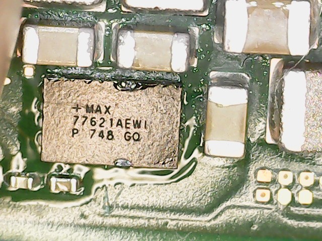
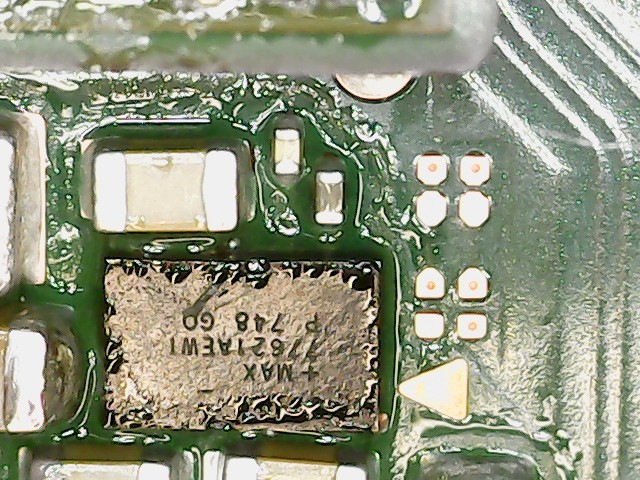
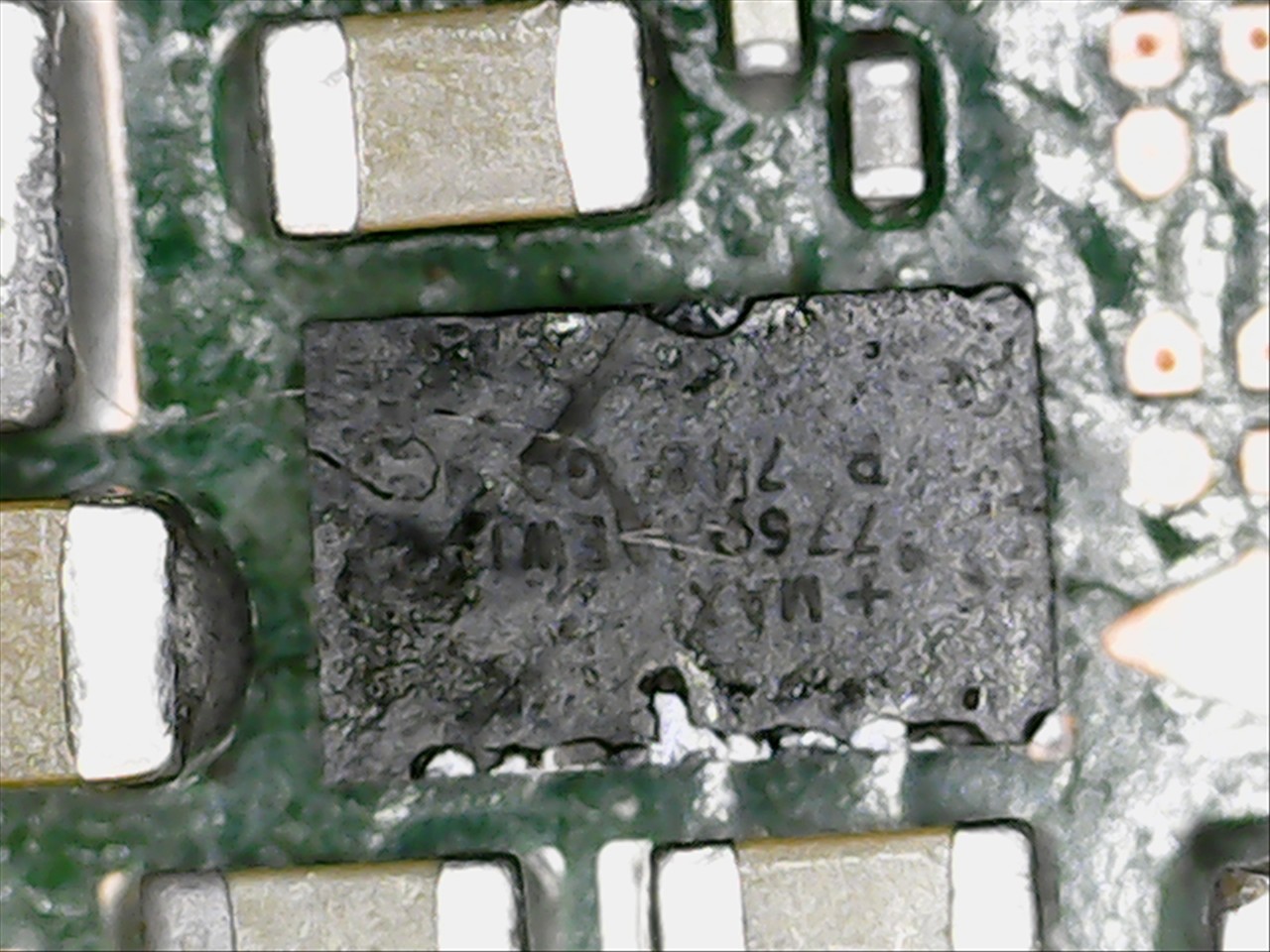
You have to be extremely careful here, if you somehow bridge VIN to VOUT on the MAX IC’s you’ll kill the SoC instantly.
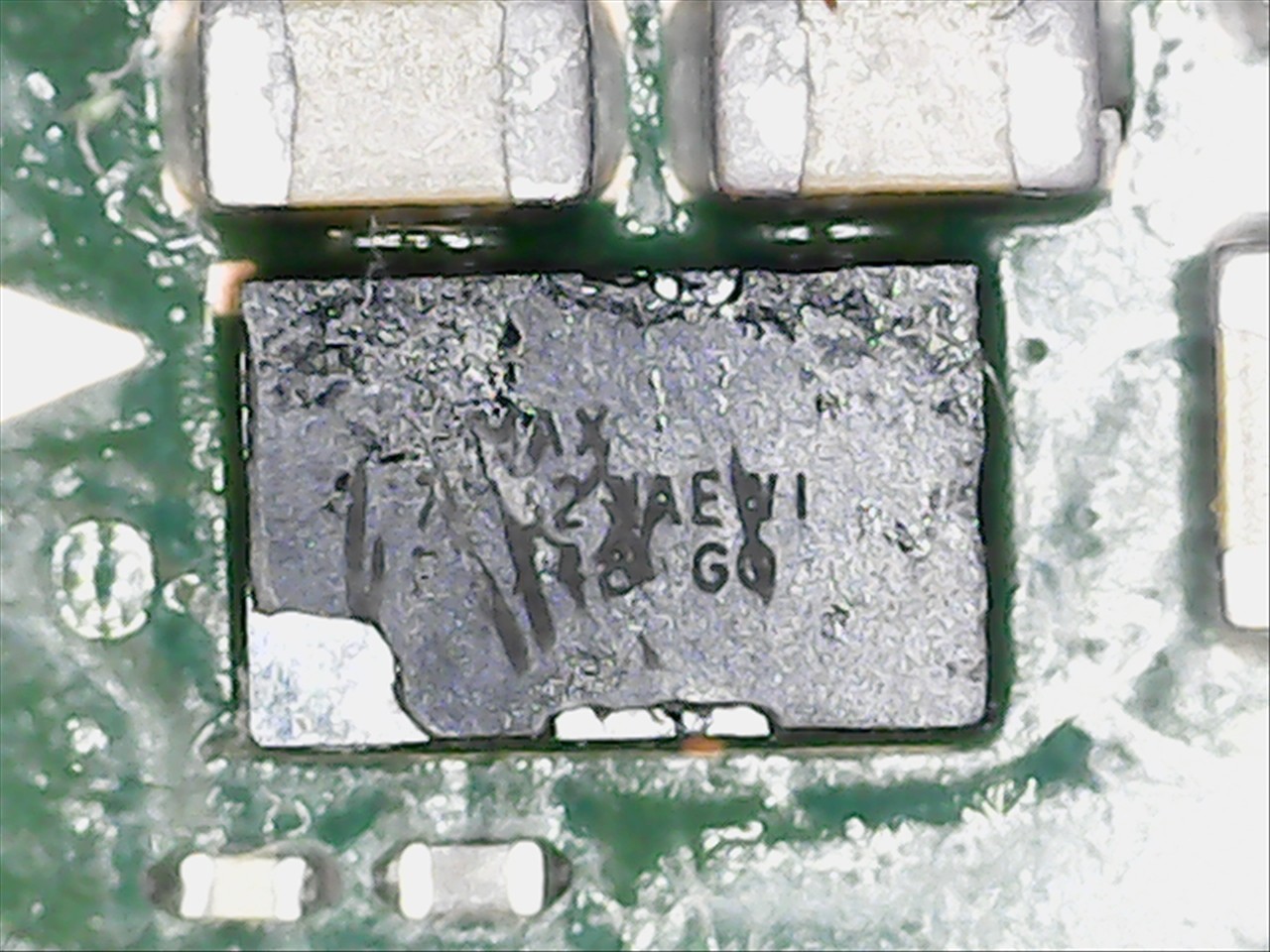
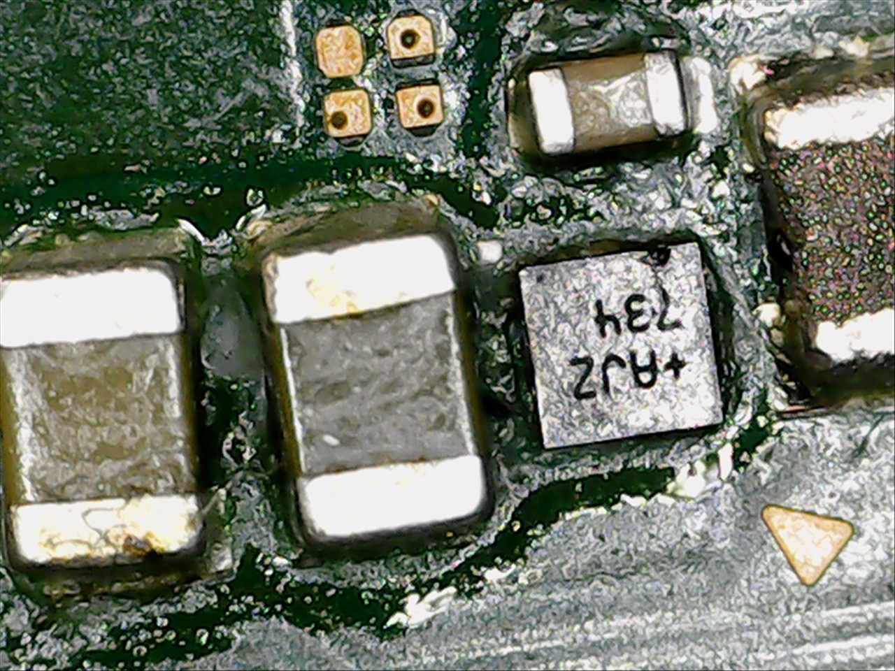
You need to check the IC’s for any physical cracks or chiips as theyr’e incredibly fragile and even the tiniest knick to the silcon/glass will cause the IC to not work (or worse) - while i can see the plastic polymer top is obviously damaged closer attention needs to be payed to the silicon below
You need to take diode or resistance measurments in both polarities on the surrounding components prior to poweing on and compare the values to a known good board so you can ensure the repair was successfull and that you won’t kill the SoC when applying power
Yeah, you have to check the SoC primary rails by measuring resistance to ground, so the two Max IC’s on the front of the board, checking resistance to ground on the inductor/s, then switching probe polarity and again taking a reading.
Then afterwards flip the board over and check resistance to ground on all inductors (both polarites) on the primary Max pmic
The above question is important though, you can’t just tin the IC’s with an iron and plant them on the board then reflow and hope for the best, they have to be reballed properly, there’s no getting around it unfortunately
Yes I did not reball them properly! I just ordered some solder balls and will have to test the SoC while I wait on those. I’ll follow your steps above. Thanks for your help!
And then I got a few more like that for Android/samsung devices etc (just search aliexpress for a set)
Then you just overlay the stencil on the IC until you have a match, pitch and pad etc
Sometimes ball count will be more on the stencil but the pitch and size is correct, so you can just use kapton tape kinda like a masking tape to cover the excess.
As for paste, 63/37 leaded… don’t buy this from china and instead get it from a verified distributor (Mouser, TME, Element14, Digikey etc)
I’m not going he expert, Calvin n Severence knows a lot more,
But I got the same short on a board, after a 3 chip removal , finally found culprit is the max chip right under emmc( the remove the chip under the soc first then the middle In the back then finally the one under the emmc. Don’t forget to remove the emmc here, waiting for a RE all kit to fix my emmc and the 3 chip to fix my board. Hope it helps