Ya I probably did I figured the chip was most likely toast so I ordered a few chips from mouser. Should get by tuesday or wednesday.
I wasn’t sure so I tried with and without. I previously replaced the usb c port so it should be solid
I was checking Calvin’s readings which were at 70 ohm but I took one of mine apart and I’m getting 48 ohm so I guess I don’t need to worry about that.
Probably irrelevant but I’m getting 6 kohm with red probe on ground on a known good one.
On a sidenote, it’s amazing how watching certain youtubers go about their troubleshooting process removing chips randomly based of off almost nothing. I didn’t see it before but I do now and it’s horrifying. If I listened to them, I would have removed half the chips on the board twice.
Might not have been you, seen plenty of cases where it’s caused from prior users.
Would be what I’d expect on an unpatched erista. Your current patient is perhaps a touch low, but still in the realms of alright (maybe patched eirsta this is typical, I forget) . Not sure Why Calvin measured 70 ohm
Yep… there is one particular youtuber (I won’t name names) but you know, the guy with the funny accent, spends most of the time jacking himself off in the video/s about how “great” he is, and what an “amazing job” he’s doing (whereas I’m looking at it in disgust) … well, this guy, if he had your patient board right now, well, he’d be clueless, not only would he give up in 5 mins, he’d also charge the customer a “repair attempt fee” for merely glancing at the board + whatever postage costs each way, and there would be no video on the matter… most of these so called “pros” can only fix obvious physical / liquid damage based on visuals or obvious dead shorts to ground, nothing more… I think when you’ve been doing this for a while, it will dawn on you that not even 50% (maybe even less) of all incoming repairs are these (obvious) fault / repair types, which gives you a clue as to there real success rate / scammy nature.
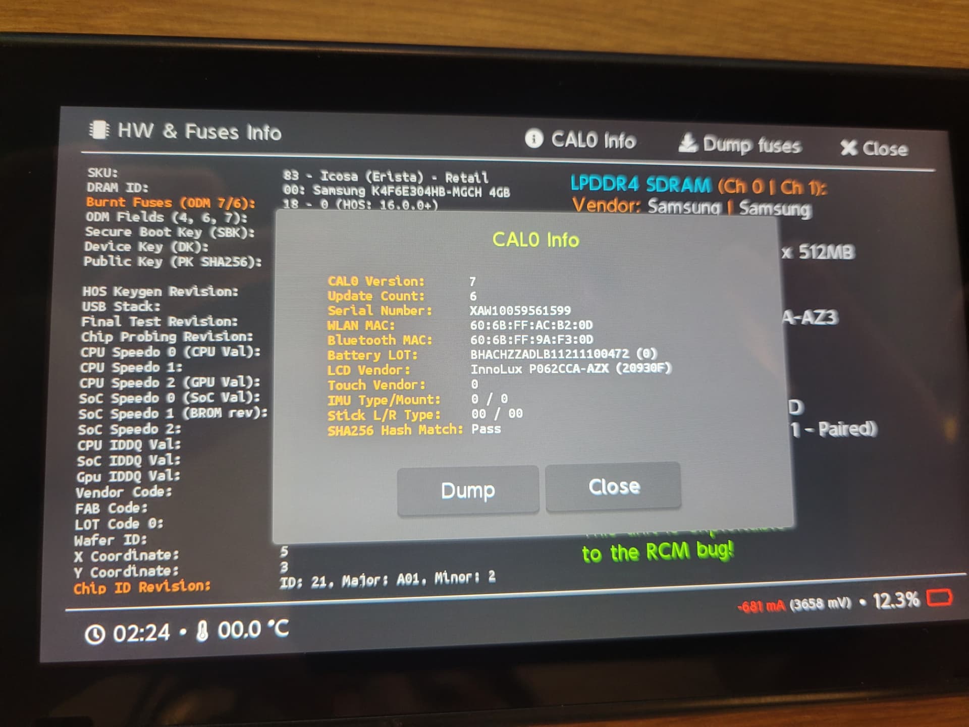
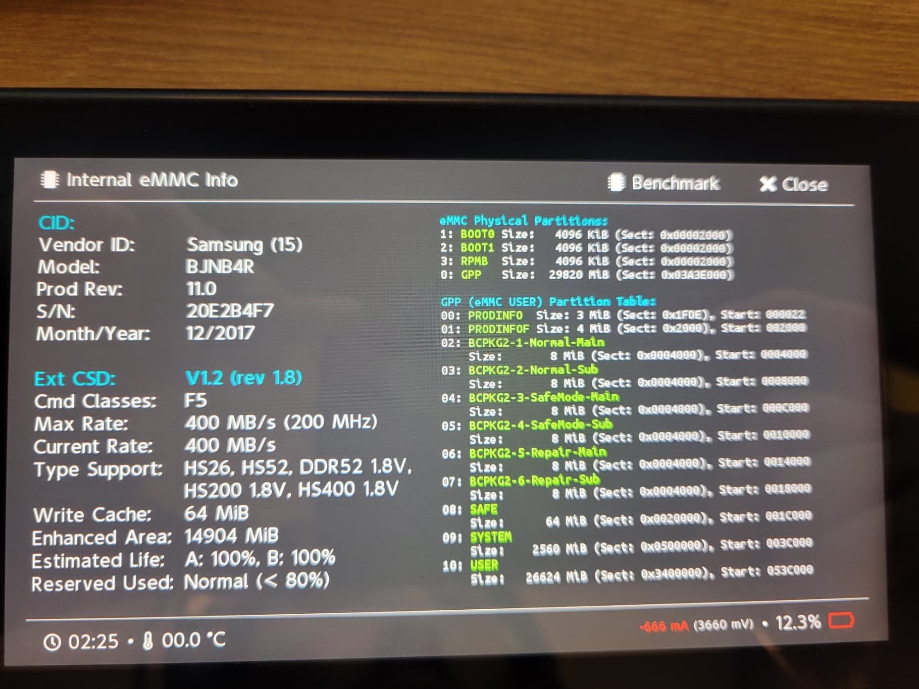
Alright I got my ENXX replacements and I’m happy to report that I’m getting 3V3 line which means all the primary rails are good to go but I can only boot to the Joycon Logo Thankfully, it’s an unpatched Switch so I can boot to Hekate. Here is what I did afterwards:
Made sure emmc is working
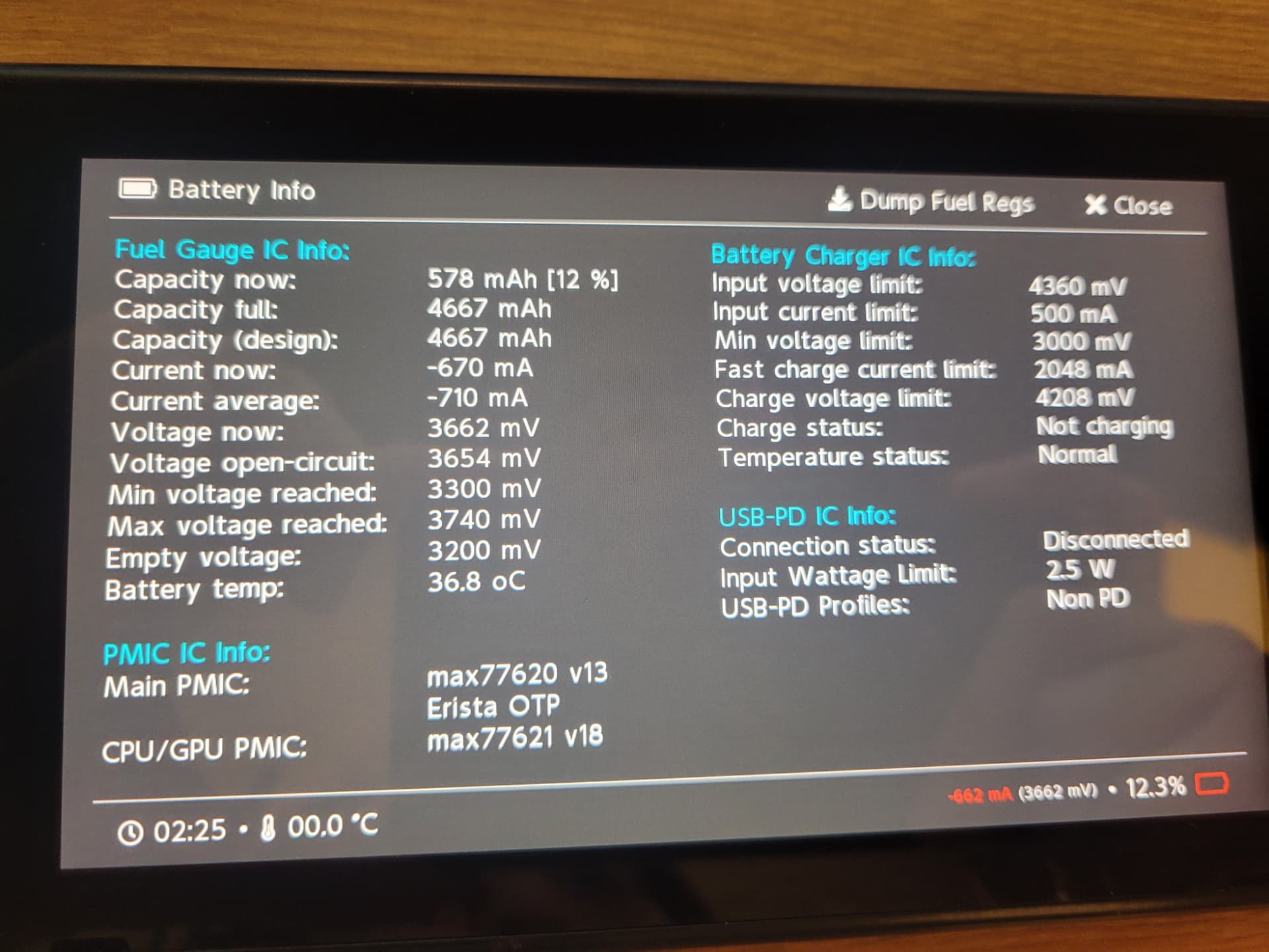
Made sure battery is good and fast charging
Checked fuel gauge and max776
Rebuilt nand with donor nand and original prod.keys
Tried Linux but it won’t boot, stays stuck on booting… (left it for 30min then shutdown, probably because of the heat)
Tried reflowing the Wifi IC
2 things I noticed.
1- Temperature shows 0 on hekate.
2- When turned on the emmc area is burning hot even though it seems to be working fine in hekate without a warning.
Also, in full transparency, before I started messing with it I replaced the Wifi IC because I read on another thread that it was most likely the source of the problem @Severence. That was before starting the thread.
I’m happy to be back to a semi-working state thanks you guys!
Refrain from powering on the board from this point. Check resistance to ground on 3V3PDR and 1V8PDR and let me know the readings.
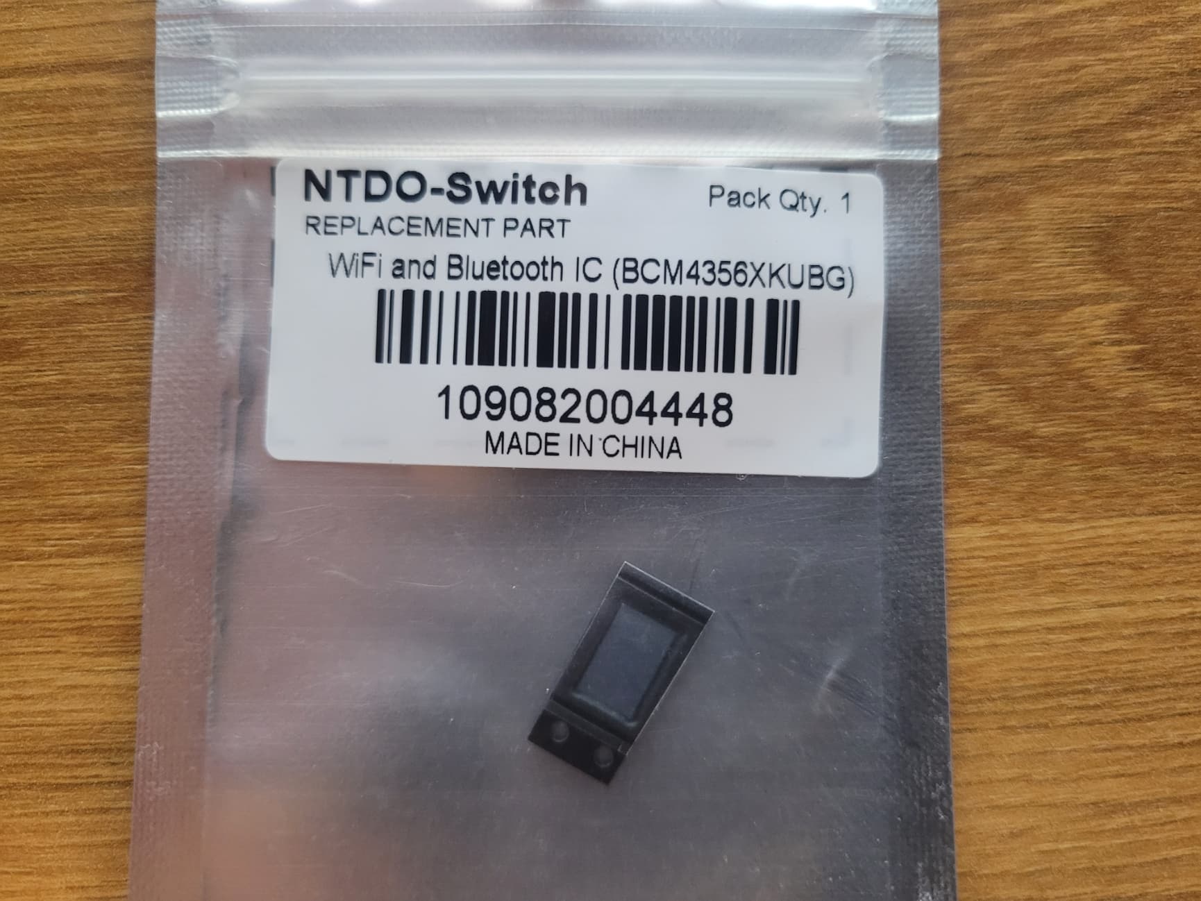
You haven’t attempted to reflow the EMMC IC too have you ? If no my best guess would be the heat is as a result of the WIFI IC reflow/reball. Where did you get the WIFI IC from?
Check TMP IC and voltages etc at this IC (use datasheet as reference) . Do this step last following resolution of the heat at the EMMC IC, don’t connect battery or power on the board until you’ve resolved this issue
Alrighty, thought I was going somewhere with my thought process Here is what I get with nothing connected:
1V8PDR: 1.56K
3V3PDR: 18K
I didn’t attempt to reflow the emmc. I should point out that I noticed the heat in the area before the reflow. Then again I did replace it so I might have messed it up. I did thoroughly clean the pads before soldering the new one. Also, I got the chip from mobilesentrix in Canada. I got a bunch of their products before and they seem like a reputable source for parts. Although I noticed you mentioned in another thread that the FW might be the problem here but it doesn’t explain not booting into Linux so there is definitely something else going on.
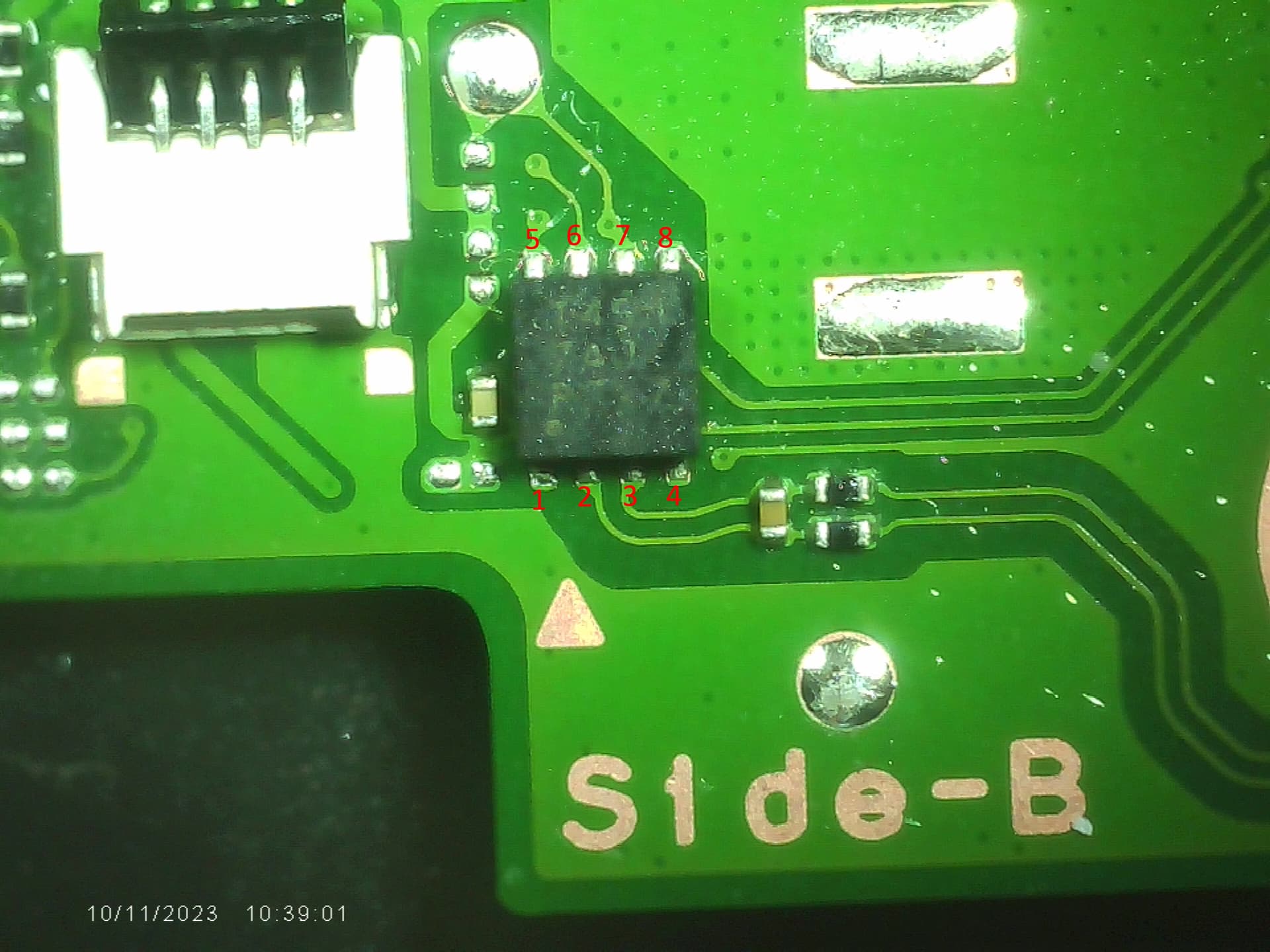
Here is a picture of my soldering as well as what I got from Hekate before disconnecting everything.
You’ll have to refresh my memory is this a Mariko rev? (I’m guessing not as your booting Hekate) In which case your measurement above is low.
Disconnect the EMMC module and take the measurement again on this rail just in case
This ones good
While your at it, can you give me the resistance relative to ground on all your primary rails (inductors surrounding the main Max PMIC on the back of the board) I just wanna verify your other Ram rail primarily.
Maybe, though, afaik you can’t buy this IC “legitimately” (ie. mouser, digikey, direct from company etc) so either mobilesentrix is pulling them from donors and reballing (?) them themselves or they have a dodgy supplier whos slipping them the IC under the table… or they are doing what the Chinese are doing and selling a completely different model IC with re-etched numbers which is incompatiable with Switch (but same pad pad pattern, IC package etc)
We actually discovered that it was infact what I mentioned above, Chinese just sold a different model IC with markings removed and the correct markings re-etched on it . L4T Ubuntu (probably android too) were perfectly happy using this IC but HOS wasn’t.
Current draw reported in Hekate seems on the high end (afair) which makes sense given we expect you have a short somewhere.
Can you take a picture of the TMP IC? pretty sure it’s VIN is 3V3PDR if I recall and it has connections to 1V8PDR either directly or indirectly… so might be related I suppose. Given the heat though in the EMMC area it would suggest you’ve potentially got two unrelated issues.
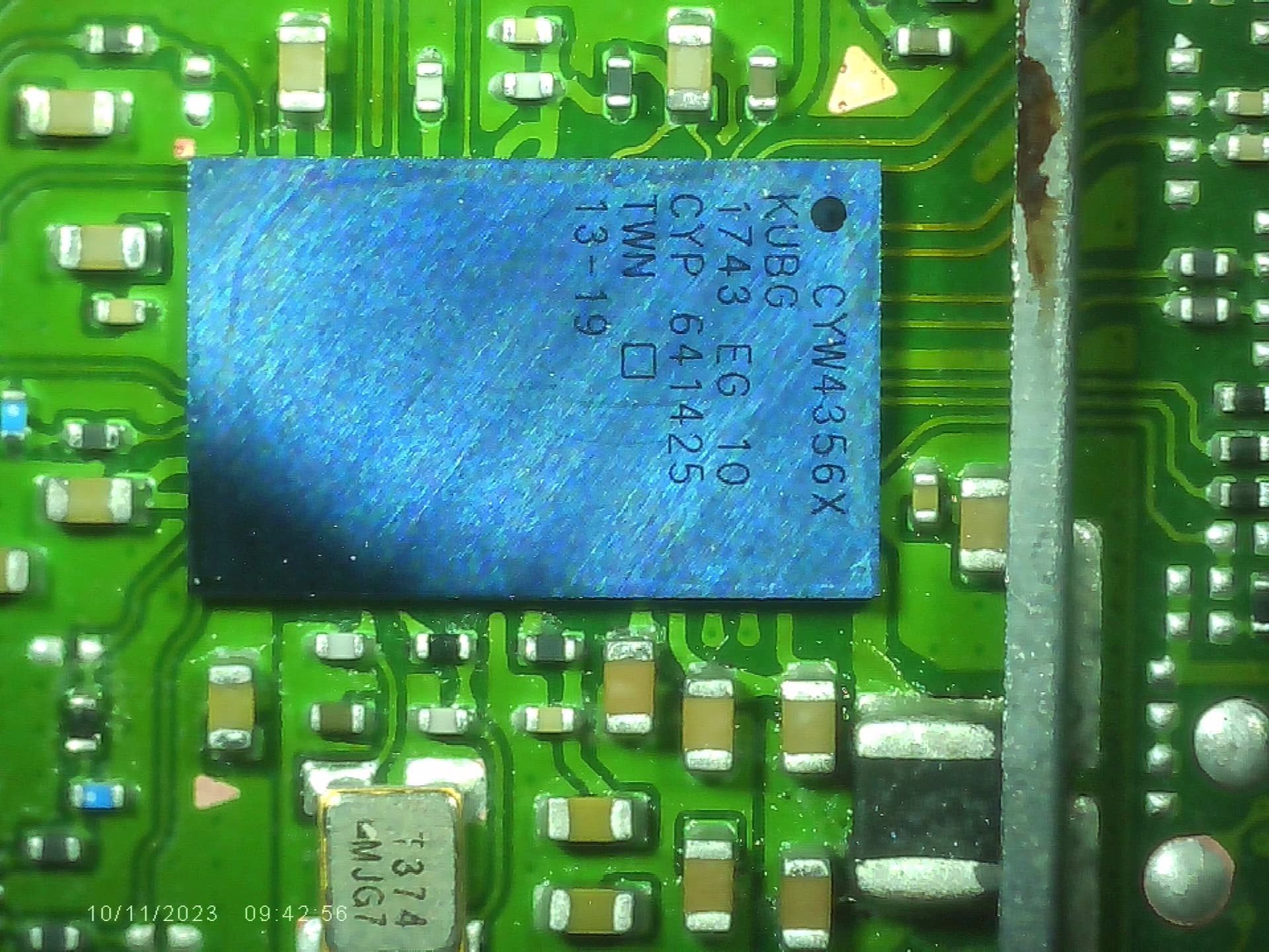
Your soldering edge on does look good btw at the WIFI IC, but hard to say. Can you give me a shot from above too? … could just be the IC was from a donor and it was bad all along as well I suppose
As for the IC, here is the picture. They seemed brand new honestly and I used their M92/BQ/P13 more than once and they usually work. Although I don’t have that much experience. I have a bunch of donor boards but I never reballed a chip and don’t have the stencils. I could try that as a last resort but it still doesn’t explain not being able to boot into Linux right?
I see, might be worth keeping EMMC disconnected and hooking up battery and prompting to boot (to Hekate) very briefly and seeing if something in WIFI IC area gets hot. (the opposite too, you could hook the EMMC up to a donor board and see if the EMMC gets hot, then you can rule it out, assuming you have a donor motherboard thats intact enough)
Everything looks fine afaict, apart from 1V8PDR, still a bit too low… though this is one rail which can be a bit tricky on some meters, if you have another board where you can measure this rail, if you get similar reading then it’s probably fine
I couldn’t say, never dealt with the company tbh, maybe someone else can chime in on this front
This is the input afair, and also if i remember correctly it’s 3V3PDR (makes sense given your resistance reading) and trace comes by way of the WIFI IC area ( )
Anyway, don’t know your measurements realative to ground here off the top of my head but nothings jumping out at me being wrong but, unless it’s flux residue on top, or trick of the light, IC looks a little suss. Might be worth swapping it with one from your donor as a matter of course. When your doing your brief power on as mentioned earlier, after you’ve swapped the TMP IC, when your checking for heat at wifi IC (EMMC disconnected) boot into Hekate and see if the temperature is now being reported with an TMP IC from your donor on the board… if yes, that’s one problem off the list, if no,
check resistance from pins 2 and 3 respectively to the other side of each respective resitor and check the resistance (just to ensure nothing is open, incl track)
I tried to plug the emmc and run linux on a faulty but similar board and emmc is fine. Tried the other board’s emmc on the toasty one and the emmc heats up. I believe because of the Wifi IC under it. When I start Hekate and launch linux without the emmc, the Wifi IC area get really hot but I couldn’t pin point the exact location as I don’t have a thermal cam.
I also noticed that the battery drained insanely fast. It was at 70% last night before unplugging it and now it’s a 2%. It spent the day of the bench Then I unplugged the battery and plugged it back and showed 60%.
I tried replacing the TMP IC but to no avail. I still get 0 in Hekate.
Resistance for Pin 2 and 3 are respectively 104k and 101k to the other side of the resistor.
I believe the wifi chip is at fault here. I checked for shorts around the IC and surprise suprise almost everything is shorted. I verified on another faulty board that doesn’t have the issues and no shorts on the caps I tested so either the caps are bad which is unlikely or the chip is bad or (most likely) I bridged the pads under it when I replaced it/reflowed maybe. Is there a connection from the Wifi chip to 1V8PDR? It might explain the low resistance value no? Am I starting to make sense?
Not a huge deal as your patient is unpatched, but for future reference, careful doing this, you can potentially blow update fuses, if the patient next time is patched then it will appear as a soft brick and will require other methods to resolve … if at that point it’s known to you.
Anywhoo, pop the WIFI IC off your patient, boot Hekata again and see if the area still gets hot. Yeah, I know it’s a pain, but it’s the most obvious choice (don’t blame me if it isn’t the culprit though )
Fuel gauge issues
Agree
Yeah most likely, probably I/O pulled up to it at the least.
You are
Can’t remember tbh (probably in the app circuit in the datasheet) but 100k resistors makes sense, so that’s fine. If after the WIFI IC removal the temp still isn’t properly reported, then swap the IC out.
Ya I took the risk because they are both unpatched and the other one had a damaged emmc so will require permanent modchip to use offline only but hey at least a kid is gonna get a free Switch if I get it working
Even if it was a shot in the dark it’s better than a slap in the face But it turns out the IC was the problem. I checked for shorts afterwards and every single one of them was gone so once again I did a shit job To my defence this bga is packed!!
I loaded Hekate without the emmc and no heat was coming from that area. Same with the emmc plugged in.
So just to make sure I took the measurements before and I replaced it and everything checked out in diode mode at least. In hekate I get all the values could it still be causing issues?
Lastly I’m still getting no temp in Hekate. I might’ve taken a chip from a bad board. I’ll see if I can salvage some more!
Assuming you replaced with a preballed IC? remember no touchy when up to reflow, just put it in place and let it fall into place naturally (same deal at the WIFI IC) The only way you can screw preballed (assuming good preballs) BGA IC installs up is one of three things (top tips ), 1: you don’t properly wick the pads and the chip starts slipping and sliding off the peaks during reflow (I think you’ve said this isn’t your issue) 2:you use too much flux and the IC floats away (could be in combo with too much air too) or 3: you touched the IC, or felt some uncontrollable urge to nudge the chip (which you don’t need to do) during reflow (tin a nearby component such as cap or resistor if your uncertain)
Failing the above (regarding fuel gauge) I suppose the TMP is also on the I2C lines, So I suppose it’s possible something is spitting out erroneous data on these lines which could potentially cause both these issues… trouble is, if this is infact your issue it will be hard to figure out without a LA or scope, though, perhaps this would be a rare scenario.
Other more worrying scenario is, the IC which has these things in common, the SoC… did your measurements on 1V8PDR improve following WIFI IC removal?
Thanks for the advice! I’m pretty sure it was too much flux as I usually end up with a floater at some point. This time, I reduced the airflow to about 30-40% and left a thin coat of flux after cleaning the pads with the biggest tip that would fit. I then lined up the chip with the top left square indicator and waited to see the solder melt on the caps around. I waited a few seconds, added a bit of flux and reflowed WITHOUT touching it and no shorts and no more heat!!
Now on to the bad news. I still get the same value on 1V8PDR. I took the measurement before replacing the IC and after. From what I understand I should get around 3k right?
I also swapped the TMP IC and nothing comes up though it came from a water damaged switch lite so might not be good. Regarding the fuel gauge I installed a brand new chip and I’m sure I installed it correctly. I messed up so many of them in the past that I learned from my mistakes! I think I kept switching battery and it might have messed up the values. I charged the battery overnight and it reports the correct value and drains about 1% every 5min with a current draw of 450mA. Not sure if I got it right but it seems somewhat normal but I might be wrong.
Way earlier I mentioned something about a missing inductor which is under the LCD driver on the back side. I replaced it but I’m not sure if that could be causing an issue. I checked the resistance and nothing came up on the meter so I resoldered and now I’m getting values at least. Though probably not related.
What else is connected on 1V8PDR? So close yet so far
be quite rare you had two bad ones in a row. Only failures I see relating to the TMP are only ever traces going to it failing, don’t think I’ve ever had the IC itself go bad. (might wanna check the voltage at the IC pins folowing prompt)
You might wanna have a search on the forum and see if you can find my post where I show a continuity map relating to the fuel gauge IC and some things to check (particularly regarding I2C lines) as it’s not uncommon for people to abuse this end of the board and cause layer seperation and causing opens (opens elsewhere too). Sorry I don’t know where this post is myself.
You talking about the 8316 IC?
I’d verify this reading by checking other board… This rail is sensitive and it’s not uncommon for some meters to botch the measurments.
Nope, somewhere around 8k/13K on standard Erista is what I’d consider good (on my meter) standard polarity. Mariko is typically half that at about 5K (again my meter) - Flukes will typically measure this rail /2 , so 5K on erista and 2.5K Mariko. (flukes are terrible). So yeah, anyway, just check on another board and see what’s “normal” on your meter, if the reading is similar it’s prob fine.
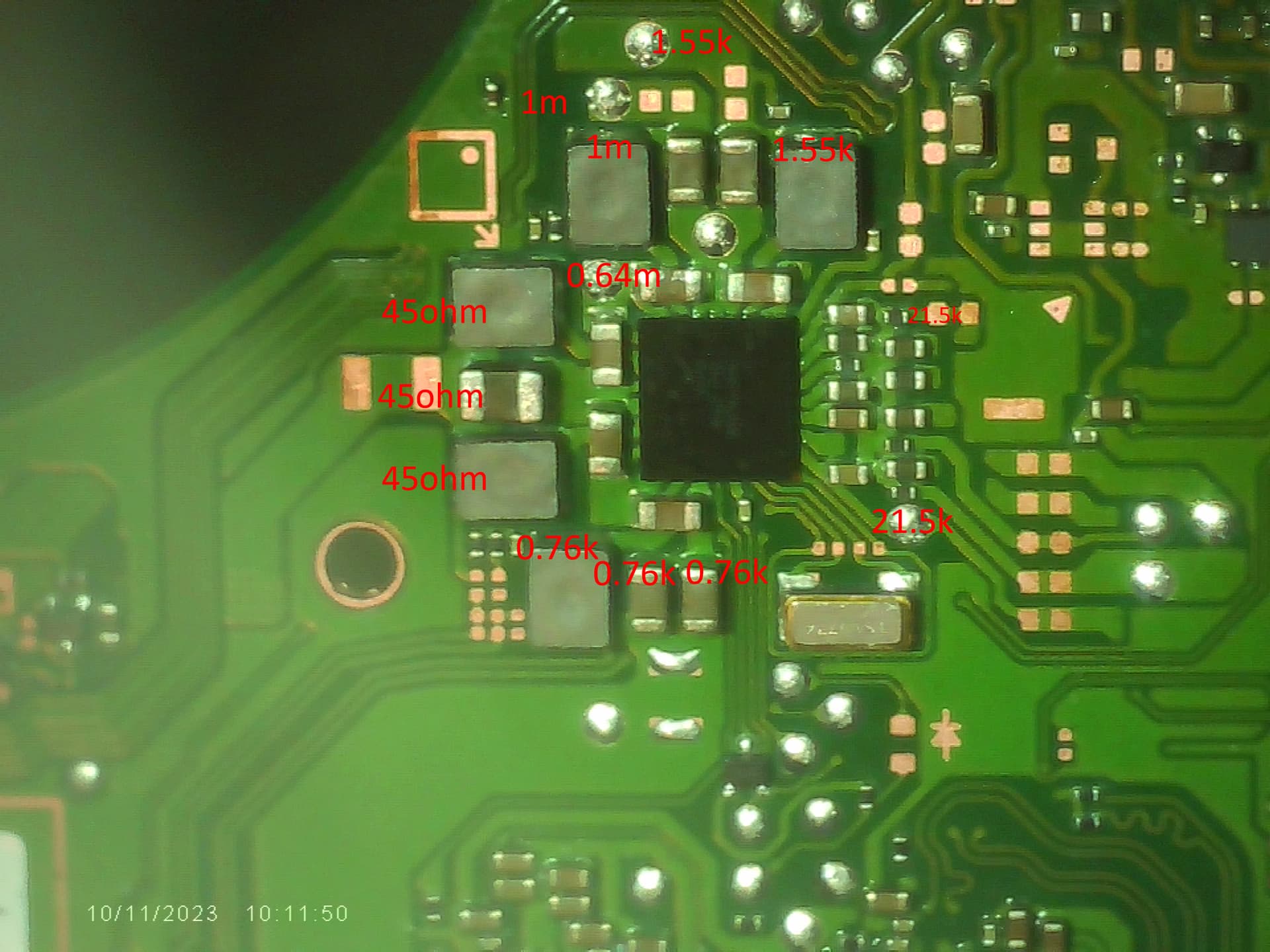
Ya what I thought too. I tried a normal boot and and interestingly enough I measured the following in order from my last pic:
1: 3V3
2: 0.4V
3: GROUND
4: 1V8
5: 1V8
6: 1V05 (1V8 on known good switch)
7: 1V8
8: GROUND
Either the 1V8PDR is tied to it and it is causing an issue with the readings or the chip itself is what’s dragging it down in which case if I remove it could fix the low resistance? Thinking out loud here
I meant on different boards I made mistakes but I still checked for continuity on the points that I could reach based off of your diagram without taking the chip and all is good on that front. I will have to remove it to check further later.
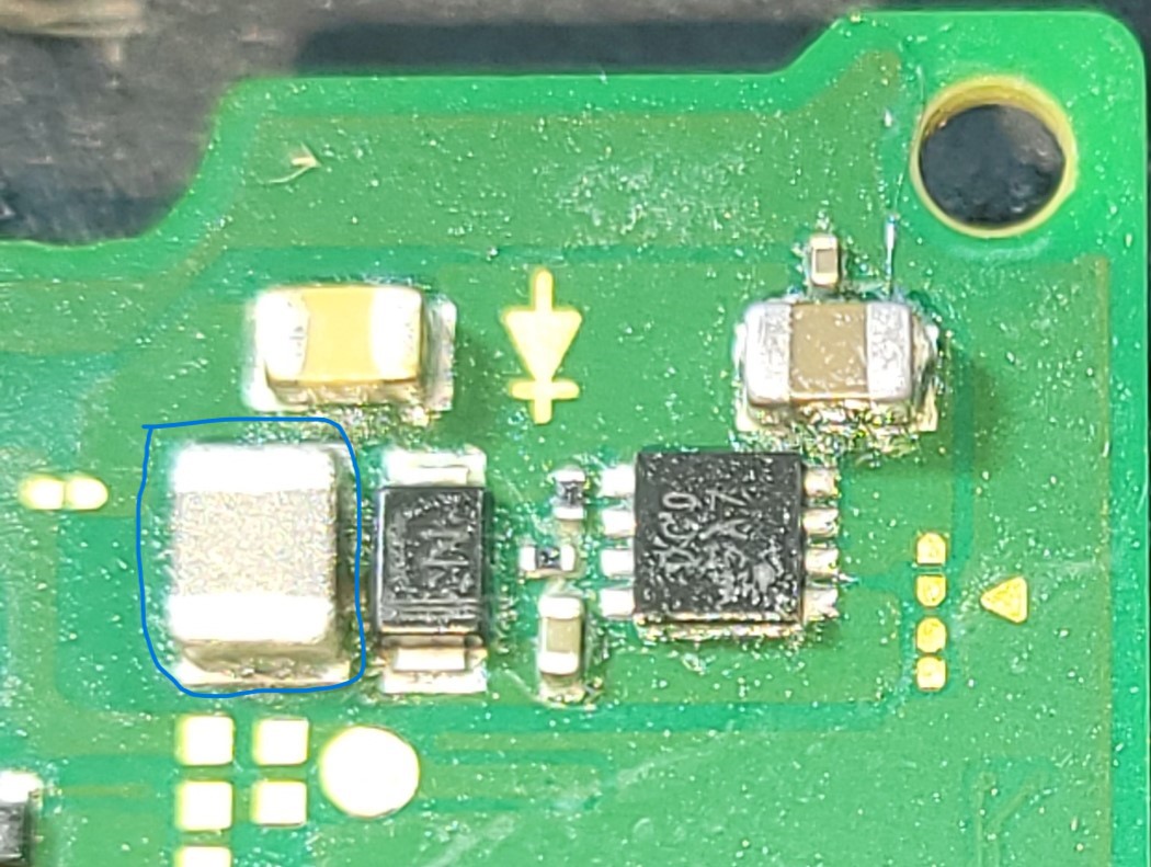
Ya the inductor on the other side of 8316 IC (circled in blue)
Since 1V8 goes everywhere, I started to probe around to see if I could find another test point where the rail passes through and I found one (I think) near the CPU. I tested for resistance and I got around 8K. Now I’m confused either I didn’t measure correctly or there is something I’m not understanding. If there is something dragging down the rail, I should measure the same resistance everywhere no? I still measure 1.5K above the PMIC. I also don’t exactly have the best meter I’ll report back when I have time to check on a known good board.
Tbh I’ve not done a lot on with I2C on Switch so I’ve got no idea what is peak / average or idle volage. May just be 1.8V constitutes a logical high and 1.05V is the idle and possibly the reason your seeing it on your known good is because active communication is gong on on this line whereas perhaps because of boot issues on your patient it’s halted … hard to say…
Check continuity on the I2C points back to your TMP IC, Audio IC etc too
Ah I see, this relates to the nearby IC which is an LDO which if I recall reates to joycon (could be wrong) so prob not relevant.
not literally everywhere, just most areas of the board
How did you determine?
Assuming it is the same rail. prob just your meter, likely meter voltage / current was teetering between the two locations and the alt location caused voltage / current to drop due to line length, junction not triggered, different reading as a result (guess )