Hey guys, I’m really at a loss here. I have a switch that was freezing at the nintendo switch logo. I checked online and figured it could’ve been the wifi chip so I changed it but the problem was still there after putting it back together. I also couldn’t get a charge but I was getting voltage all the way up to m92. I figured the chip was faulty so I decided to change it along with the usb-c port and here is where everything went south.
I put it back together and couldn’t get an image so I took it apart and took measurements and couldn’t understand what was going on. Starting from the bottom, I’m getting OL on the VBUS line. I’m also getting OL on most pads on m92.
I started a few month ago and I’m trying to learn how to properly diagnose/fix electronics. So far I’ve been able to fix 9 out of 14 switchs I bought with the help of legends on this forum!
M92: 1 = GROUND 21 = ol
2 = ol 22 = 2.48 mΩ
3 = 100 kΩ 23 = ol
4 = ol 24 = ol
5 = ol 25 = 4.17 mΩ
6 = 19 kΩ 26 = ol
7 = 2.08 mΩ 27 = ground
8 = ground 28 = 3.03 mΩ
9 = 2.5 mΩ 29 = 100 kΩ
10 = 100 kΩ 30 = 100 kΩ
11 = 260 kΩ 31 = ol
12 = 0.61 mΩ 32 = ol
13 = 0.60 kΩ 33 = ol
14 = 135 kΩ 34 = ol
15 = 100 kΩ 35 = 7 mΩ
16 = 18 kΩ 36 = ol
17 = 9 kΩ 37 = ol
18 = 1.56 kΩ 38 = ol
19 = 125 kΩ 39 = ol
20 = 145 kΩ 40 = ol
Alright so weird thing is most values keep jumping up and down. I might be doing it incorrectly but I disconnected everything and put the meter in resistance mode (Ω), black probe on ground. Am I doing something wrong? Sometimes I get VBUS at 300 kΩ and sometimes in the mΩ range.
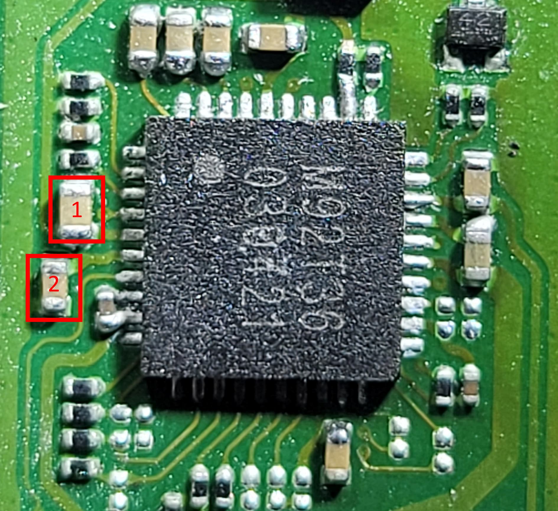
Can you post a picture from your m92t36?
The readings are very odd. If pins 5, 38, 39, 40 are oL, the corresponding caps must be gone completely. If a cap fail, it normaly shorts a line to ground.
Hey, sorry I didn’t mention it before but these readings were with the chip removed . Here is a picture. I checked for shorts on the caps around and everything seems fine.
This explains the odd readings. To be sure you can measure capacitance of the caps. Black probe on the m92t36 center pad and the red one at the pad towards the m92t36. The three and the one next to them have 1 µF and the top on the left 4.7 µF, down left 68 µF.
The capacitance on all the caps are good. I replaced the chip, measured again and now I’m getting all the correct readings for m92. I’m also getting vbus at 0.5v in diode mode. It must’ve been bad soldering on my part I presume.
I also noticed that I wasn’t getting 15v from the charger and now I am so that’s good news.
I believe I had a problem with bq so I took it off, cleaned the pads and resoldered. Pin 10 = 0.19v Is that normal? It should be 0.3v I believe. Everything else reads fine.
I did the same with p13 and everything checks out in diode mode with no shorts.
When I plug it in, I get no reading on the charger but as soon as I plug in a battery I get 5v at 0.6a charge which is the first time it actually showed anything on screen.
I accidentaly moved the fuel gauge. I’m waiting for a replacement in the next few days. I feel like I just came back to square one :S
Sorry for the basic questions, I’m still learning to troubleshoot.
Pin 10 is the current limiter for the input. I would check the resistor for correct value (220 ohms) and if resistance is ok, I would check the soldering.
I messed up yet again! The value is correct I was looking at the wrong one it seems. Pin 10 should be 0.117 and I measured 0.190 so should be fine. Also the resistor above is 220 ohms.
I’m making progress it seems. When I plug the board, it charges at 5v 0.1a (PSU can’t output 15v)
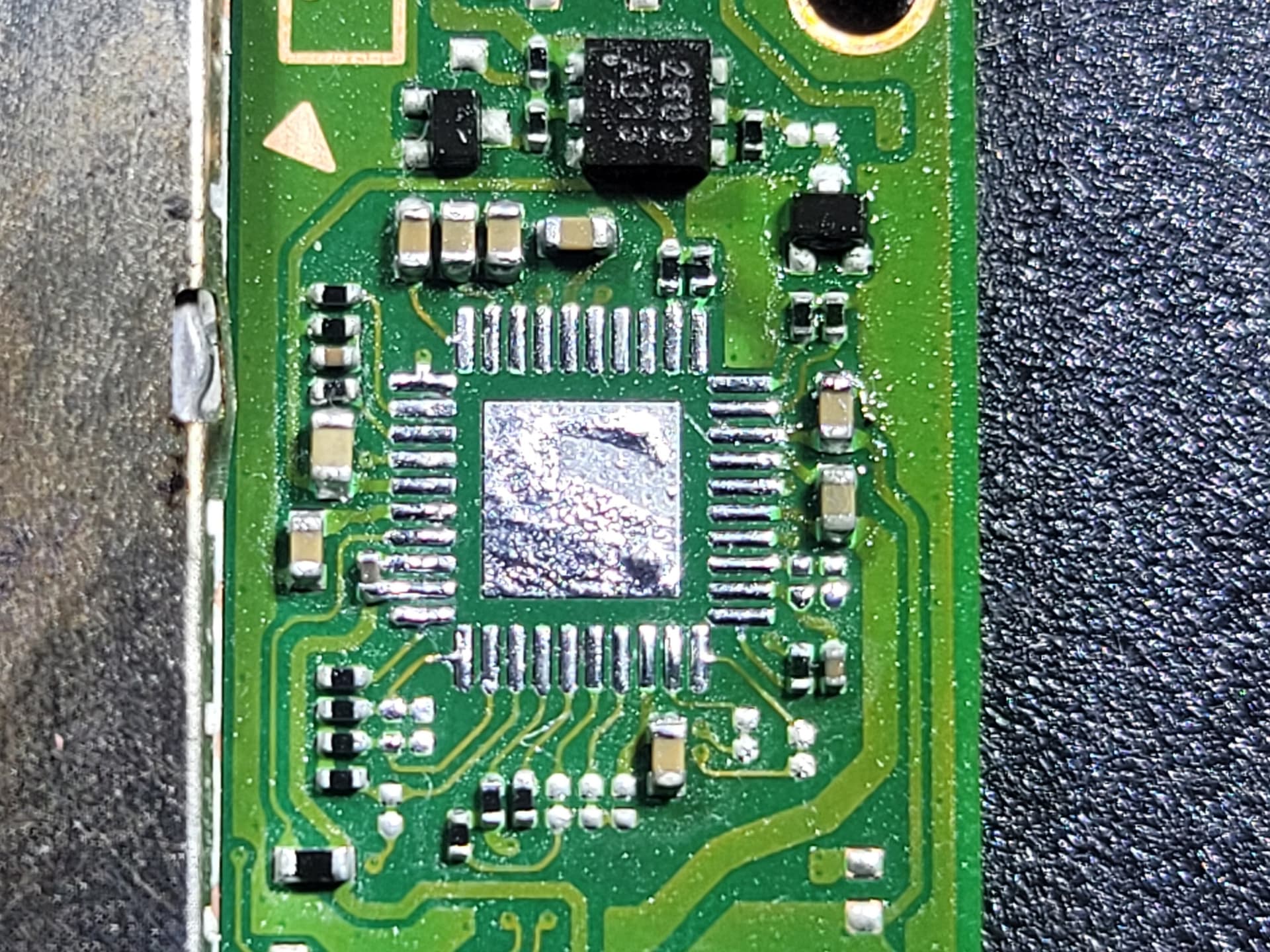
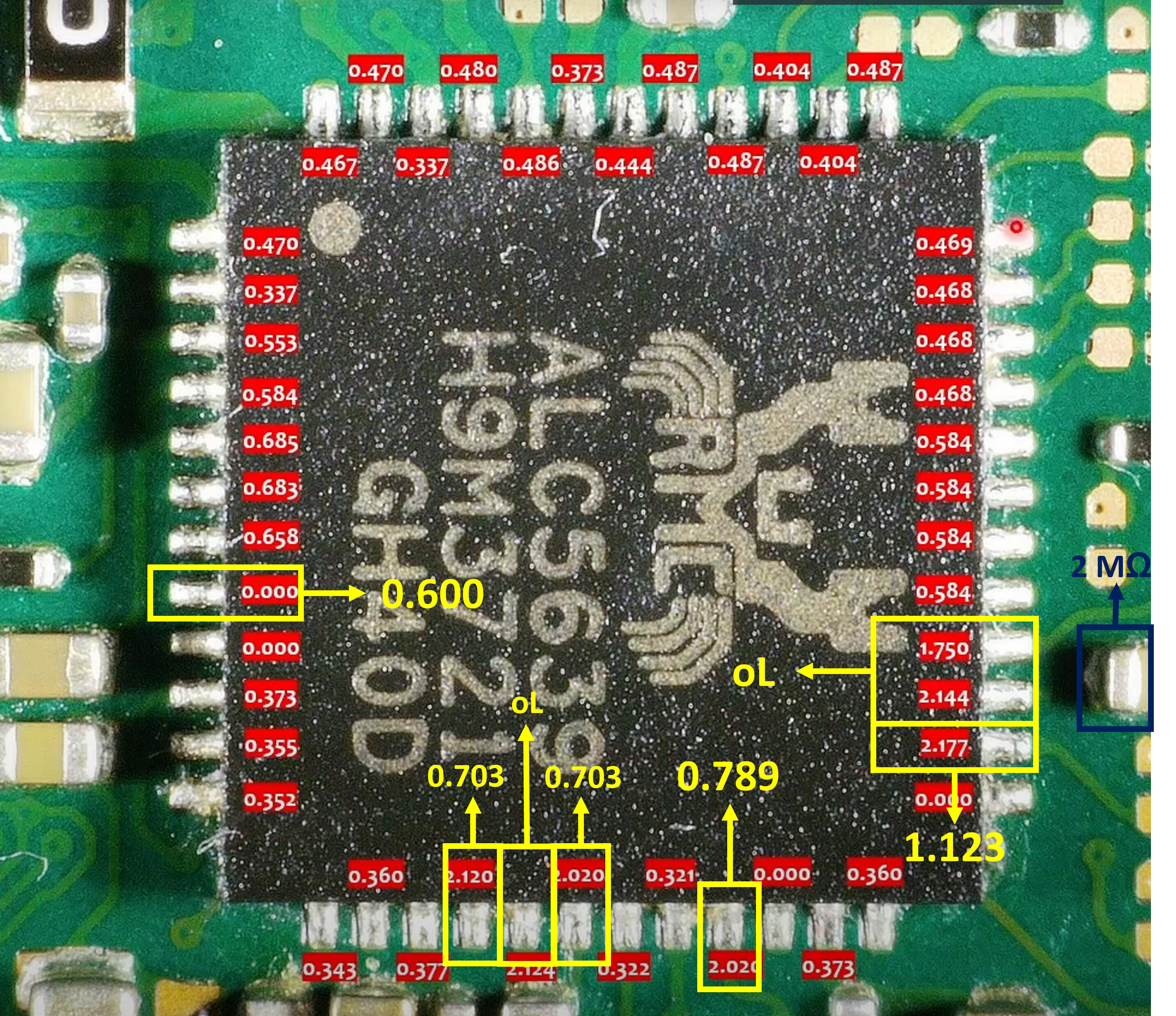
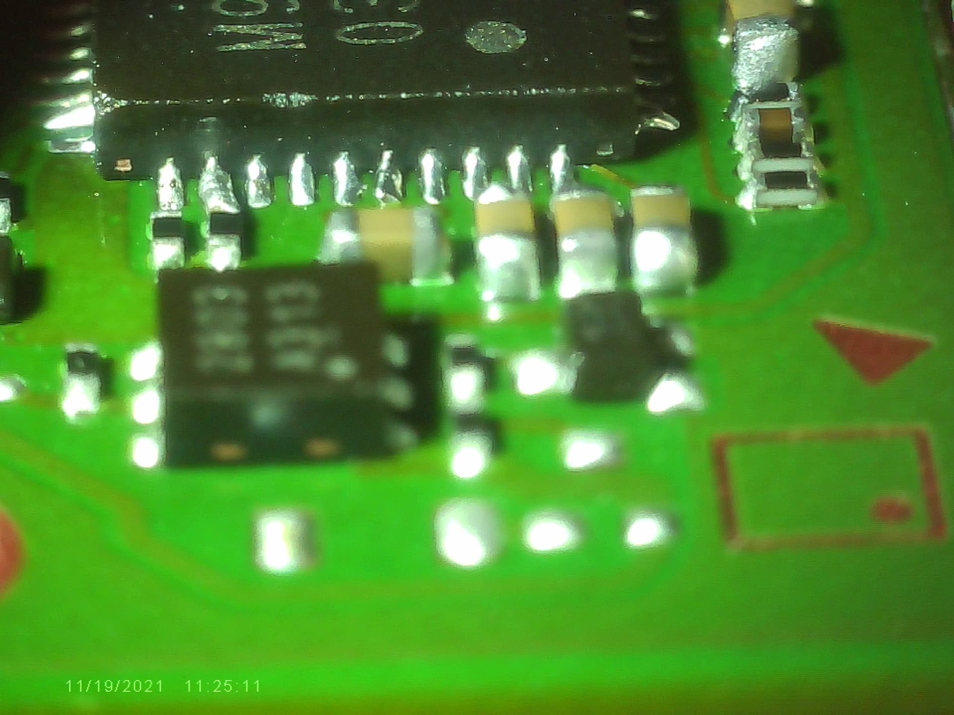
I checked the voltage regulators around the Soc and everything is fine. As well as the fuel gauge that I managed to temporarily solder back on flush on the board. I’m getting weird values around the sound chip. Not sure about the orientation so I included a picture of the affected pins.
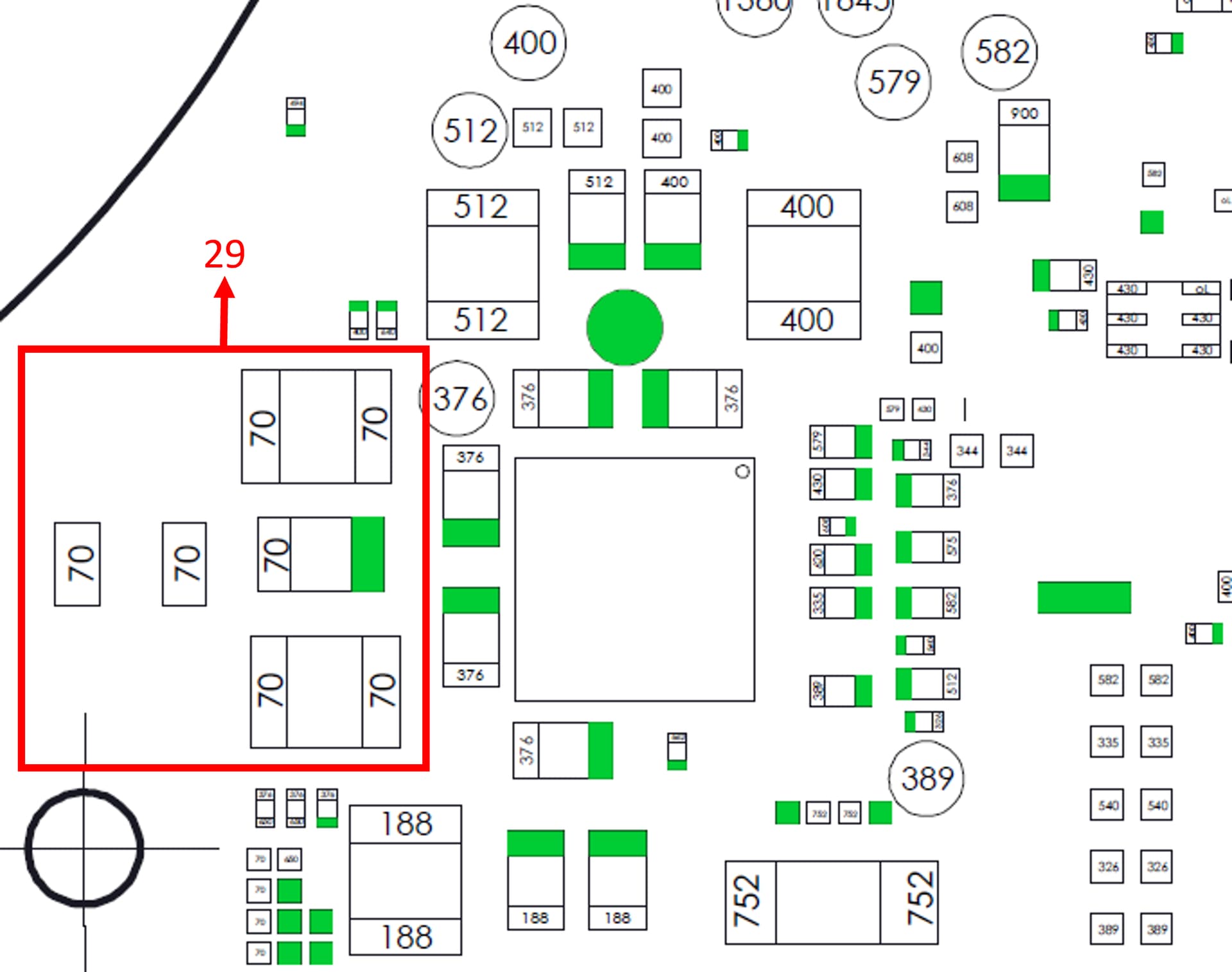
I also went around the PMIC and noticed that a few inductors were reading lower than expected. The 3 inductors on the sound chip side read 0.029v instead the 0.070v you shared in another thread.
Not sure if it’s due to my meter or if it’s being dragged down by something else.
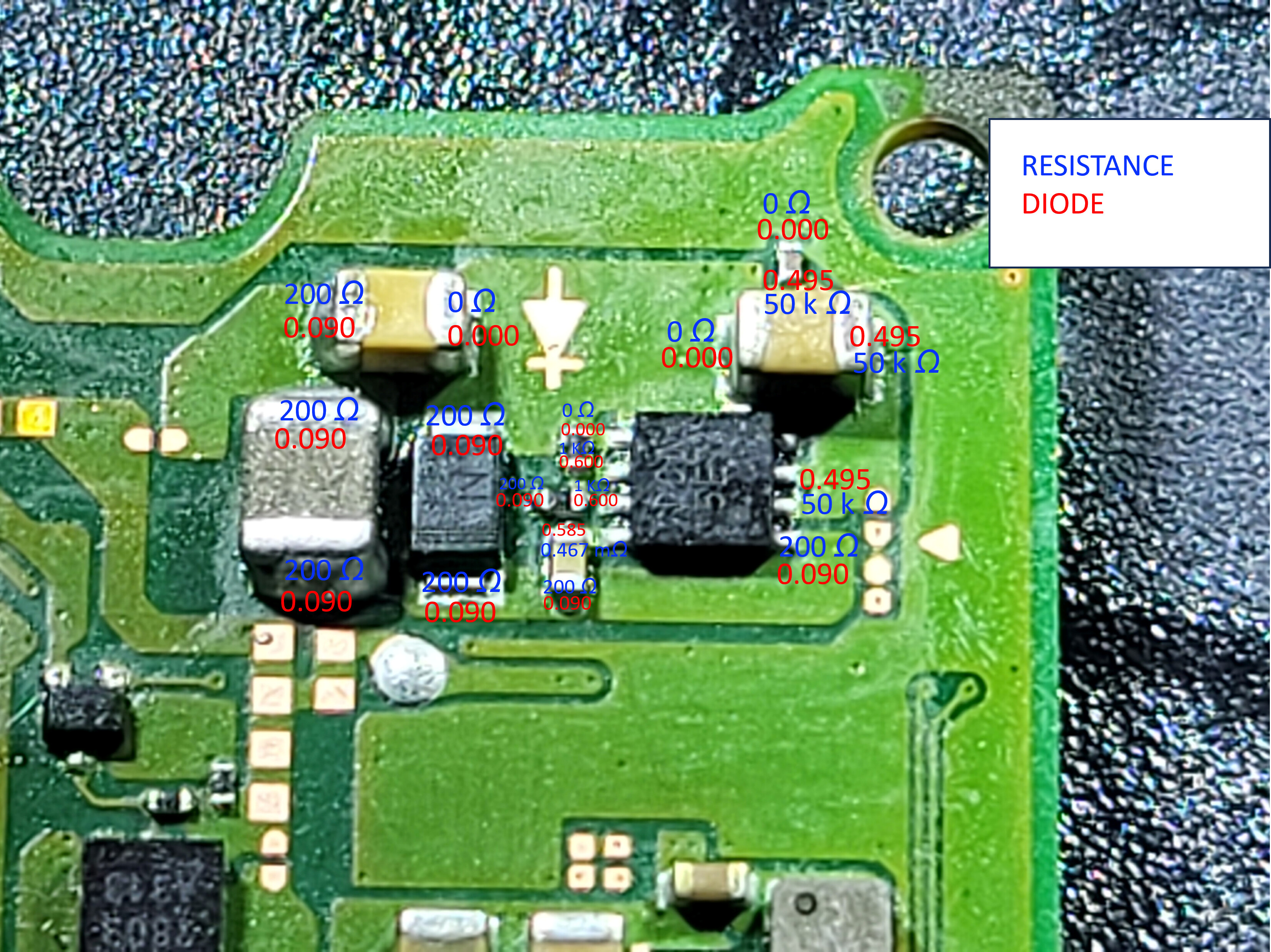
Last thing I noticed was and inductor missing in this area so I replaced it with one from a donor board (top right back of the board). I don’t know what they do and I’m not sure about the values but the big cap has much higher value than the one on the left in diode mode.
(Take all this as constructive ) You seem to be conducting your dianosis in a backwards manner, your randomly checking things on the board, your using diode mode, your trying to dianose things when you don’t even know what the thing is, Your checking every single pin of a given IC etc etc.
You need to start from a framwork that’s top down and then hone in from that. So, instead of checking random things all over the board, instead, check the most primary rail on the machine, then start checking other primary (sub) rails, where you can typically see, sub sub rail issues which can then narrow down things further
Check this topic here
and this one,
Would be indicating you have USB/M92 issues (or some other USB related circuitry) or that you have a short on SYS or some other closely linked rail, a large majority of which can be ruled out by checking the rails mentioned in the previous topics
I would be checking continuity from USB to destinations (via USBC Breakout board) following checking of all rails.
This is no good man, I’d order up some more IC’s (from legit source like Mouser) and replace this properly less you potentially cause damage elsewhere on the board.
No worries at all! I appreciate the info honestly! I know I’m all over the place. I have no prior training so I try to look for information on forums but usually is specific to an issue so when I have an issue with something I don’t know I’m stuck hence the questions. I have been repairing electronics for 20 years but never at a component level but I’m super interested to learn how to troubleshoot methodically. I don’t do this to make money but rather to save electronics that would otherwise be thrown in the garbage. Maybe one day I will but for now I wouldn’t feel confident or comfortable doing it.
ps: I did order some fuel gauge ics from mobilesentrix but I’ll confess I’ve also ordered a few chinese chips. I should probably refrain from doing that in the future as its probably causing more problems :S
Alright, I checked the rails to the best of my understanding and I have 1v8, 1v1, 4.2v, 1v35, 1v05 but I’ missing 2v9 and 3v3. All the measurements came from different test points around the board as well as caps and inductors around PMIC.
From what I understand, 3v3 is generated by EN8N voltage regulator am I correct? I measured the caps around it and they output 0.75v instead of 3v3. One of them outputs 4.2v. On the other side of the board I have 5v coming out of the top cap on the left of M92 which is supposed to output 3 to 6v right? The bottom one outputs 0.75v and I should have 3v3 from what I gather.
Next step is checking for a short on the 3v3 rail with a bench PSU but I don’t have one at the moment. Is that correct? or am I missing something?
Am I in the right direction with the measurements I’m taking?
Re-read those topics I linked you to previously, votlage (outside of knowing if it’s present or not) is largely not relevant (PMIC and others are capable of delivering / handling extremely high currents)
Correct, though, the marking will typically be different on the last two digits, so typically people refer to it as ENXX IC.
What is (and this goes back to checking those other topics again) the resistance to ground on the output? If it’s not shorted, is the enable high? (this would be another search term )
That’s probably SYS
Dunno, which cap are are you talking about?
NO! this is retrosix wiki dumb that’s rubbing off on people … what is a short? , a “short” impies a fault, and is a connection from one place to another, in the case of the “fault” we are typically talking about a short to ground. How are shorts measured?, well again, a short is a connection from one place to another, so resistance from one place to another… What is the unit of measure for resistance? it’s Ohms not diode / connecting up a PSU
Also, just a sidenote, I’m pretty sure (if I’m remembering right) USB will not prompt the console to boot without M92 installed (somebody correct me if I’m wrong) so if your relying on the USB to do this (as opposed to the pwr button or other) and if M92 IC isn’t currently installed, then this might explain why 3.3V (3V3PDR) isn’t present when you expect it to be.
LOL ya no retrosix had nothing to do with it! It’s just my dumb logic But good to know I can’t trust him! So resistance to ground close to 0 = short right? I don’t have that on any of the caps or inductors around the main chips on the board, namely, PMIC, BQ, P13, MAX, M92 but I don’t understand the values yet.
I’ll keep reading. I hate to bother when info has already been shared! I’ve been scouring this forum since April and I can’t believe I missed the most basic stuff.
Thats ok, in the sense it’s not being dragged down, bit of an unusual reading though, would ordinarily expect it being somewhere around the 18K mark or maybe 130/160K (depending) … Maybe it’s just due to your M92 IC not being properly soldered,
Fine
would be 3.3v, suggesting it’s not being prompted to boot, or ENXX IC isn’t being told to turn on.
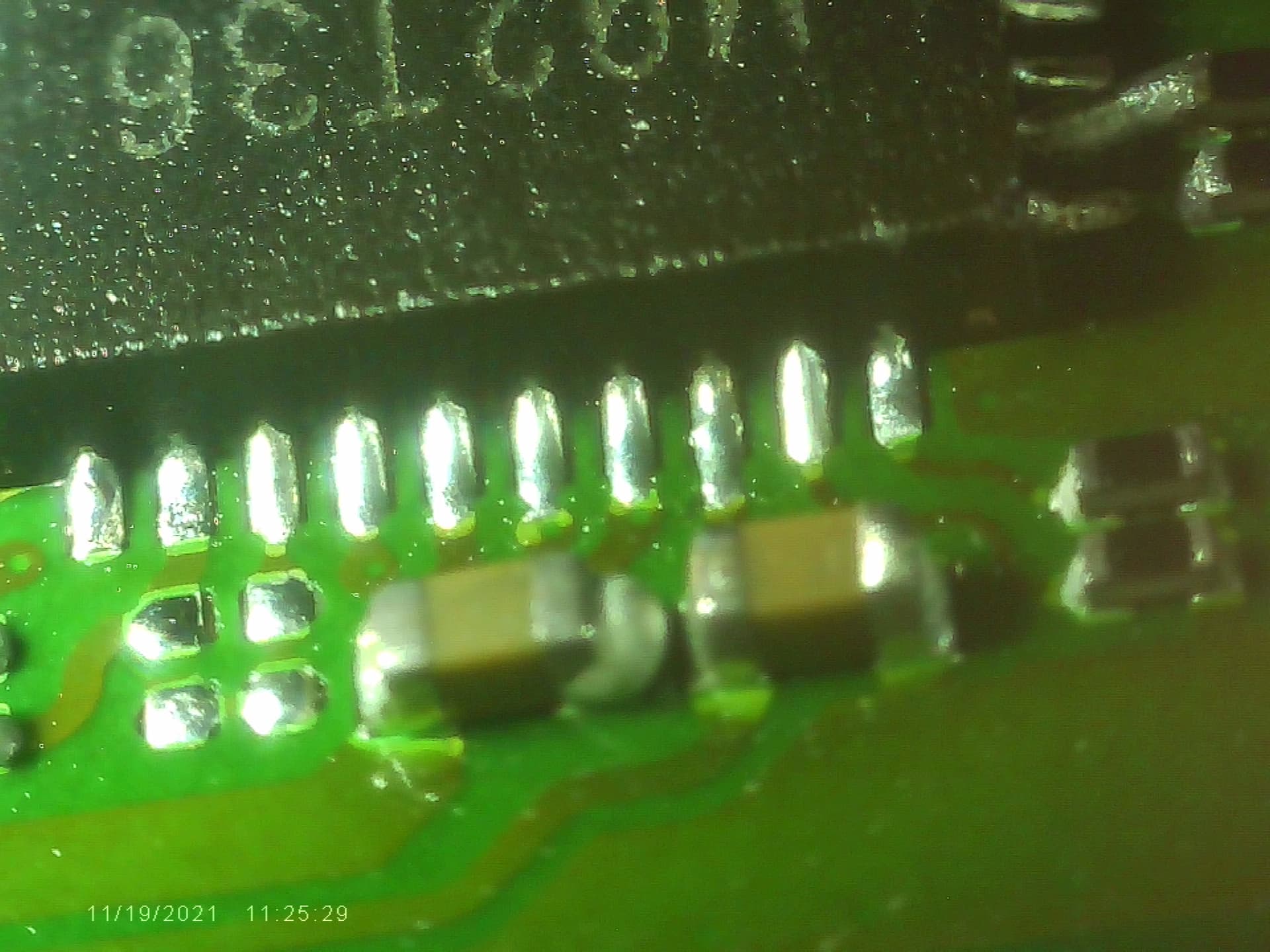
Yeah looks a little iffy, might be worth taking a shot of the pins/pads on edge so i can get a better look
This is a little open to interpretation / user terminology. Me personally, I’d say “dead short” for something which is virtually zero or very close ohms (to gnd for example). I’d say short or soft short for something whih is out of the ordinary / fault that is low ohms (to ground for example), so depends on the person, but yeah, close to zero is a short or “dead/hard” short.
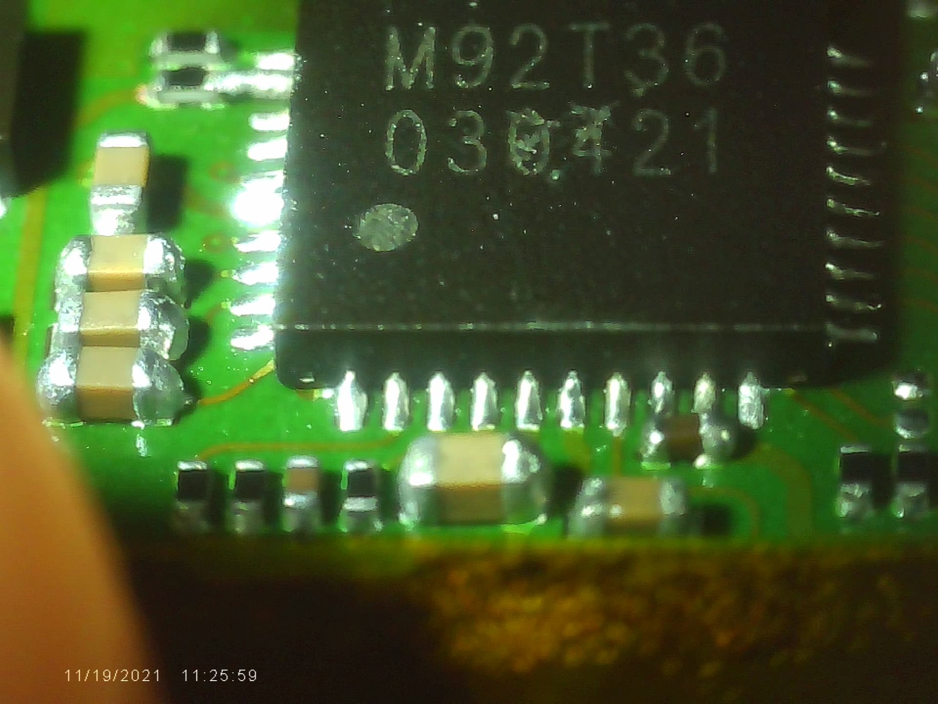
Here are the pictures. Not gonna lie, I reworked the pads with the iron because they looked a bit dry so these should be fine. As for the cap, I’m still getting the same value of 0.75v Also, I remember you mentioned in a another thread not to press down on chips but I cannot figure out how to do it correctly without pressing. If I let it flow by itself, usually not all the pads make a connection. I try to tin the pads as much as humanly possible but it never seems to be enough. I have no problems with bga chip for some reason! Go figure…
Sorry for the solder blobs here and there. Still getting around working with smd
Sorry about that! I meant that I checked resistance and I didn’t find any dead shorts but I did notice, as I previously stated that the left side inductors around PMIC have a lower value than usual 37 ohm which would be considered a fault?
Are you making sure it’s prompted (ie: connecting USB or pressing power button)? If yes and still nothing, check for the enable at the ENXX IC following prompt.
This can take quite a bit of practice. In an ideal world, you’d use a stencil for M92 IC etc (let’s be real, we can’t have a stencil for every single IC), without, and if your having trouble, then a run round with the iron just after IC reflow (while things are still hot) will take up the slack and give near perfect joints (no pushdown neccessary).
Right, because the solder is predefined in that case (the chip has no choice in the matter the volume) and your not (or shouldn’t be) touching it.
than usual relative to what? 37 ohm would be about right on an original rev Switch, lower still on Mariko (assuming your talking about the boot CPU rail)
I tried by connecting the usb cable and by shorted the power connector and measured afterwards. I read from one of your posts that D2 is the enable pin under ENXX and is connected to a 100k resistor on the left of it. I prompted the board and checked the voltage on the resistor and I’m getting 1v8 on the left side and 1v7ish on the right side which is the enable, correct? Does this mean it’s not prompting the chip to enable and deliver the necessary voltage? Also should I have a battery connected while doing this? Also I can the 4.2v gets delivered through ENXX and then to the coil under since I’m getting 4.2v on both sides. It then goes back to ENXX.
I was just comparing values from a known good switch but it is an Erista so it might be nothing to worry about and yes, I was talking about CPU Boot rail.
Coming back to this one. I meant the 2 caps right of ENXX but I gather you got it. The weird thing is I’m getting 18 kohm with black probe on ground sometimes and other time I get 18 kohm and I also get 90kohm. With red probe on ground I get 1.25 kohm or 4.15 kohm. Should I be getting the same value on both sides?
I’m starting to see a little clearer thanks to you
Nope, opposite. Your console is prompted, the enable at the EN IC is high (1.8V) and this enable is basically telling the EN IC “hey, dude, turn on your output” , if your not getting your 3.3V out, then somethings up with the IC or install (usually people cooking the opposing side of the board at M92 cause this) So I’d pick up some of these IC’s on mouser or other and just swap it out.
You had the USB connected, so SYS would be present, but it would be preferable in future to hook up battery when checking voltages, as, after you’ve prompted the console to boot, certain rails come up (3V3PDR being a good example) - if you USB (just for example) was intermittent / dodgy and if you had no battery hooked up, you could lose prompt effectively (or power as a whole or intermittently) , without realising and start down a path of chasing your own tail.
And what were you reading on your other board?
This is good, always wanna keep black on ground by default
The jump up is pretty typical on this rail, and relates to charging something up and/or triggering a junction, though as I say, the jump is usually to somewhere around 130/160K … probably nothing to worry about, or could just be because the IC is bad etc
If you mean vs when having black on ground, then no, you’ll getting a different reading with red on ground as your applying voltage to the board negativer bias.
Cheking reverse polarfity as you’ve done can be handy when honing in on certain suspicious rails (as you’ve done here) and your measurment in this polarity do seem a little on the low end… though tbh I don’t know the measurment epected like this off the tope of my head but it’s kind of beside the point atm, as I think we’ve determined something is up with the EN IC at this point