Black screen after closing switch with HwFly RP2040

Hello
I have the same problem as you have with your switch although i didnt get any resspberry display just black screen from the start(after i installed the chip) and red solid led light.
Even after removing all modification still have black screen and nothing happend.
Did you have any update of your issue?

I know you all want a one click solution to this problem but there isn’t one, in order to help I need rail measurements as I mentioned here or over on this topic

or the many other related topics :smiley: - I’ll summarise, If the Switch console isn’t booting without the modchip in place then we have to assume the following, 1: the EMMC is physically dead, or 2: the EMMC partition data is corrupt, or 3: hardware fault on the mainboard.Or a combination of all three.

The measurments I ask for can probably identify 1 (to a lesser extent), and 3 (to a greater extent)

2: would require verifying the EMMC data which I’ve covered in the topic here too and/or ensuring modchip hardware is good and then properly installed to potentially resolve, but this requires that 1 and paritcularly 3 have been verified prior (to avoid potential permanent damage)

In the case of the OP, his boot0 parition on the EMMC in all likelihood had been corrupted, we now know that almost for sure, why? because he would have been able to boot stock and seen a boot logo and/or the console would have booted without the modchip in place but he could also have additional hardware issues which could possibly prevent boot too (which the measurments I asked for will all but confirm) and that’s not even taking into account fringe cases, for example, what if one of you guys installing these modchips has chipped the fuel guage IC unbeknownst to you or me (which has similar symptoms) :man_shrugging:

Regardless, if you aren’t capable of providing the very basic measurments I’m looking for (so I can help you) or you aren’t capable of a bit of a initiative and reading and searching through a few forum threads to make yourself capable… then quite simply you shouldn’t have even attempted the install to begin with (sorry, not trying to be mean but it’s the truth)

:+1:

Hi, I have almost the same problem - *== after picofly on my patched v1.
I have full backup, could I write required partitions using another hacked pathed v1 or v2? Either I need unpatched to do this. Thanks for answering.

You could connect the patient emmc to another hacked switch and mount the EMMC with Hekate over USB and on PC and write the said partition using nxnandmanager :+1: (easiest way of doing it)

Curious, did it work for a long period, or start acting like this early. Or did it behave like this following an update?

If you do write the partitions, start with the boot0 parittion on it’s own first and if you can let me know if this resolves your problem, as I’m curious if that’s the running theme in these cases.

Although this assumes your backup is the same HOS version number as what the system was was actually on at the time of the problem. If they are different versions you’ll have to write all partitions.

If the backup is indeed a lower OS version, then it’s possible you’ve blown the update fuse (you’ll have to check on this if the modchip prevents this by default) if the backup is a different version and if the fuse has blown then you’ll need to use a modchip on your patient again to get it out of this state or alternatively if you have your keys you’d have to generate the files for the version your Switch was on at the time of the problem or just the newst OS version

Hi @Severence,
I returned following a break (unfortunately, only a small part due to the summer holidays). Nevertheless, I am on my way to take measurements.

I don’t know if this message is directed at me, however, so far I have never complained but rather always politely asked and thanked for the support… and I continue to do so :grin:

Having said that, I borrow the images from the topic Picofly installed worked first time niw switch fried of the person who has the same problem as me, and write my own readings instead. All readings are with EMMC attached to the board.

Also:

dd8636a060695a4845c7472cd6f842d2492d74d4_2_690x393
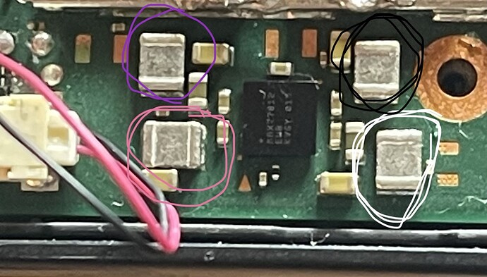
white both sides 57Ω
Purple both sides 12.6 Ω
pink both sides 12.6 Ω
Black has no reading

f0a7455e347045e005ca2176b4727170c8319174_2_374x500

White both sides 14.4 Ω
Yellow left 14.4Ω, right 0.2 Ω
Blue both sides top 14.2 Ω

Peach top 16.2 kΩ
Orange top 16.2 kΩ, bottom 0.4Ω
Cyano top 4.22 kΩ, bottom 0.4 Ω
Black both sides 4.22 kΩ

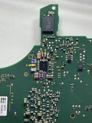
Purple boths: bottom 9 Ω circa and top 0.5 Ω
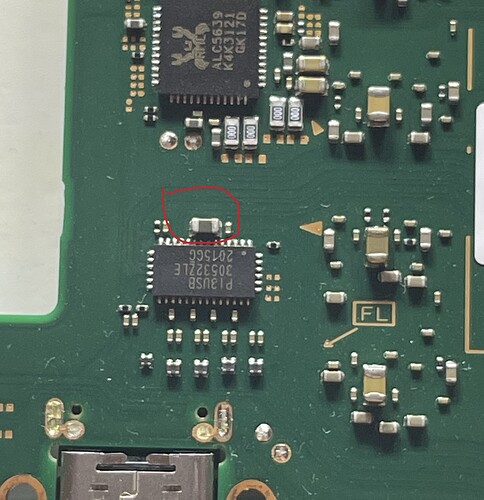
Red 8.8 Ω

6e25de1fb9d804b27c345cb58cca7fdeac08b145_2_690x389
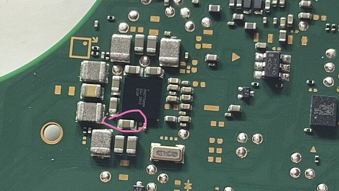
Pink is left >20 kΩ (gets bigger every second, goes over 100 kΩ easy), right 0.4 Ω

70201d35572f48151fa864ff683a752a151e7d5e_2_484x500
Red left 125 kΩ circa, right 0.4 Ω

Correct me if I am wrong, but from reading your comments in the other thread I guess that my readings are good, do you confirm?

Let me know if more readings are needed, I’ll leave the motherboard disconnected for the time being.

If the problem is not the EMMC and the hardware readings are fine, it’s even more likely that the problem is on the partitions, right? Hoping for Boot0 and possible to recover (so far I’ve just tried once to write a Boot0 and Boot1 generated on my own, before getting the ones from @jkyoho)

As always, thanks in advance :smiley:

Hi @jkyoho,
I wanted to come back also to this.

I was comparing the Boot0 you provided with mine.
Apart of the difference in size (1,5 MB yours, 4 MB mine) I also see there a difference in the amount of data (I was thinking that most of 4 MB were just zeros).

On the left I’ve put mine, on the right yours.

On the Top, the amount of data finishes at same offset and looks also pretty the same.
However, yours closes at 0017FFF0 but mine continues for a while and have some data!

Also, I can see a weird plain message at the bottom of my file (don’t know if is relevant):

> Hardware alarm %d already claimed ***PANIC*** Hard assert, no program space


But maybe is just a debug string and %d is actually replaced with a digit in case of needs.

Do you know if data after 0017FFF0 are actually important? Or can I just try to write your Boot0 and Boot1 as it is on my EMMC (once we assured there is no hardware problem)?
Remember that I can only flash via ubuntu using the MmcblkNX, don’t know if may cause problems the shrinked file sizes.

Haha, nope again, just stating it in general. I don’t recall if I touched on it here or in the other thread, but I mentioned this is probably going to become a bigger issue for others in the weeks or months to come, which unfortunately seems to be the case :frowning: and unfortunately, people with not enough experience too it sems :cry: I’ve got no issues helping anyone who is willing to learn :+1:

I don’t have a Mariko rev out of assembly to test but using another topic as reference this seems fine

Good, secondary CPU rail fine :+1:

Fine afair, don’t remember what this rail/line is

All one and the same rail in question (boot CPU rail) - all fine for a mariko rev :+1:

One and the same, fine

perfect :+1:

Damn, almost had all of them :frowning: Second Ram rail (but of course also has SoC I/O implicated) , this is such a shame and I’m not even sure the cause. Pop your meter in continuity and find the caps (possibly plural, I forget how many) on the SoC which correlates with this rail (red) and take an extremely close look at them for any junk around them or solder spatter, or signs of heat etc (I’m really clutching at straws for you here) I might even be tempted to knock these caps off to take them out of the equation (only if your comfortable and sure you aren’t going to make the problem worse)

I mean, failing this, I guess you could pull the main PMIC and see if this clears, then after pull Ram… but I expect it’s going to be the SoC in this case. given your other rail measurements it’s highly unlikely that the EMMC would be causing this rail (in red) to be getting pulled down as a by-product as the EMMC’s two rails are measuring perfectly fine (though might also be worth doing just to rule it out, ie. disconnect the EMMC then measure red again)

Perfect :+1:

All but one :frowning:

I suspect you have two issues, I suspect your EMMC data is corrupt, and I think you have hardware issues. which one caused which fault is hard to say, but you know my feelings on the modchip and the voltage it exposes the switch board to, which again unfortunately tracks with what your measurements I’m afraid

pretty much those 00 data is not important since emmchaccgen does not gen empty data but hekate or mmcblkNX dump entire boot0/1 partition as image so that 4MB with empty data at the end IMO.

I also see this kind of ANSI note on a working Switch lite boot0 dump from Hekate.
some kind of log maybe

is this only on boards which have had the modchip installed, as then the error kind of makes sense given the modifications to boot paritions

YES, but let me quickly dump one clean v2 boot0 straightly from mmcblkNX reader

Oooh no, this is so sad!
By removing the EMMC, the measurement is still the same.

Could you highlight with a circle the area where I should look?


By pulling the main PMIC and Ram, do you mean by desoldering them? Would a reflow change something?

Cannot edit the message anymore but I think you mean the surrounding caps, the ones closer to the IC, right?

It’s the caps on the SoC (the area you’ve soldered the modchip flex too, one or more of those caps correlate with the rail red in question) you should also remove that flex btw and take the measurement on red again (just in case) assuming no change, then to find the caps I’m talking about, you’ve got two options, 1: black probe on ground, then red probe at the caps, look for the one/s that’s giving you the 9 ohm reading, option 2: put your meter in continuity, one probe on red (the the inductor by the PMIC), and the other at the caps and look for a virtually 0 ohm continuous path to the caps in question, either / or

yep, the Ram and PMIC would be the only other two major IC’s which have this rail in common (other than the SoC) - I find it largely unlikely it’s going to be some random passive on this rail at fault…

Nope, if anything, you’ll probably only change something for the worse

Hopefully you can tell from what I wrote above, it will be one or more caps on the SoC wafer. If your still having trouble then I’ll highlight, though you’ll still have to narrow down with your meter as I don’t recall them off the top of my head

CONFIRM clean boot0 has no such ANSI log at 003F7500 address. That’s said those data belongs to boot0 written from modchip

1 Like

Interesting, thanks!

I’ve desoldered and clean up remain of flux etc… The reading on read is still the same. There was small amount of thermal paste around caps on right side.

I think I’ve found the caps related to the RED one, you can see from the picture
WIN_20230920_20_51_03_Pro

I think they are, as sometimes the reading for RED changes a bit (9.5 ohms for example) and they have it too. Does it sounds legit?
I have no idea why they are impacted, as I never touched them.

You may notice the cap which is the left one to be soldered on modchip flex is not in a great state, but still gives me same readings as the past.

Let me attach some pictures. I am sorry if the quality is not great, maybe with natural light will be better!

WIN_20230920_22_01_04_Pro
WIN_20230920_22_04_02_Pro
WIN_20230920_22_04_13_Pro
WIN_20230920_22_04_24_Pro

Also my readings on the bottom ones are:
WIN_20230920_22_04_02_Pro

Black left 0.3 Ω, right 14.1 Ω

White top 0.3 Ω, bottom 13.5 Ω
Grey top 0.3 Ω, bottom Ω 13.5 Ω
Red top 0.3 Ω, bottom Ω 13.5 Ω
Orange top 59.8 Ω, bottom Ω 0.3 Ω
Yellow top 59.8 Ω, bottom Ω 0.3 Ω
Green top 59.8 Ω, bottom Ω 0.3 Ω
Light cyano top 59.8 Ω, bottom Ω 0.3 Ω

Blue/ dark cyano left 13.8 Ω, right Ω 0.3 Ω
Pink left 0.4 Ω, right Ω 6.75 kΩ

Yeah. What might be worthwhile doing is, checking to see which area / side represents the lowest, what I mean is, maintain a consistent ground throughout (ground pad at the USB for example, and I mean pad here, not the USB steel) and with your other probe measure the inductor in question back near the main PMIC, note the reading to the last decimal, maintain your ground and then take your red probe and measure any of those caps you determined are on this same rail and then note the reading. If it was lowest at the caps on the SoC wafer then most likely the SoC is responsible (your then welcome to try pulling those caps off as a last ditch hope :slight_smile: ) if the reading is lower at the inductor, then the problem is most likely the PMIC.

Worth noting though, there may be one other location worth checking the above too, the caps running down the side of the Ram IC’s, one of them may be on this rail too. If you identify any, you can do the same thing as above, if it’s lowest there, then you know it’s most likely Ram at fault :+1:

Don’t worry about these :slight_smile: they are just basically re-iterating the rails you checked earlier at the much more convenient locations :smiley:

Also @minimanimo after you’ve checked those measurments mentioned previous. Can you let me know about the SoC die in your pics, is it just a trick of the light (?) or is there solder on the die, or has liquid metal been used? or is this just some shiny thermal paste? Just asking because it looks odd, but like I say, could just be a trick of the light :slight_smile:

Hi @Severence,
I am going to try and check these.

I think is a ram fault: I forgot to mention, but when the modchip was booting (post #68) I’ve tried to run multiple payloads. As suggested, I’ve tried to run usm-loader and is the only payload able too boot and get something on screen. This usm-loader is a piece of code that uses IRam (integrated in the Tegra?). So, if is the only payload to load, then is possible to assume there is an issue with the Ram.
I think our measurements also confirm this. I’ll look for some shorts, but I’m not exactly sure where to look.
Do you think a problem with the ram can be solved?

I think, and hope, it is only the effect of direct light. I took the photos shortly after removing the modchip and cleaning everything with alcohol, so I think this is it

With less light:
WIN_20230926_19_11_43_Pro