Hi guys.
I also have a patched switch and i have the following problem. I had error 2101-0001 and i solved the error with exchange M92T36. USB-C port was broken - damaged pins and i replaced it with a new one. After replaced it, i saw that switch it not charging. I checked the USB-C port and it is ok, so i changed that too BQ24193, but the same result. When i connect it to the laptop, i don’t hear the USB device connection sound, but with RCMLoader Jig if if I put the Switch it to RCM mode, then I see the connection between him and the laptop, respectively nintendo switch APX mode. If I start it normally, he doesn’t see it. I tried with the multimeter to measure around BQ24193, but i’m not so good at the measurements and i don’t realize if something is wrong. I do not know what else to do, to solve the problem with the usb charging. Any ideas ? I apologize for my bad English and thank you in advance for the answer.
What is the charge amperage right now? Any shorted capacitors?
I measured as much as I can and started with the battery I have 3.8V and to M92T36 on the pin 5, have 3.4V and on the pin 6, have 3.8V. I tried with the multimeter to measure around BQ24193, but i’m not so good at the measurements and i don’t realize if something is wrong. I changed two USB C ports and the same defect. I didn’t find capacitors in short…
OK…but what is the charge amperage? Do you have a tester that you can plug in and see what amps it’s charging at?
Today i changed P13USB with a new one and the same result. Tomorrow I’ll buy one and I’ll have to see what amps it’s charging and come back with information. Thx !!
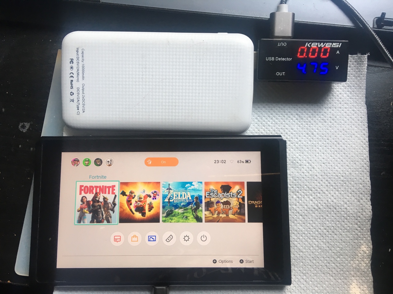
I came back with new data, after I put the tester that measures the amperage. I attached the picture.
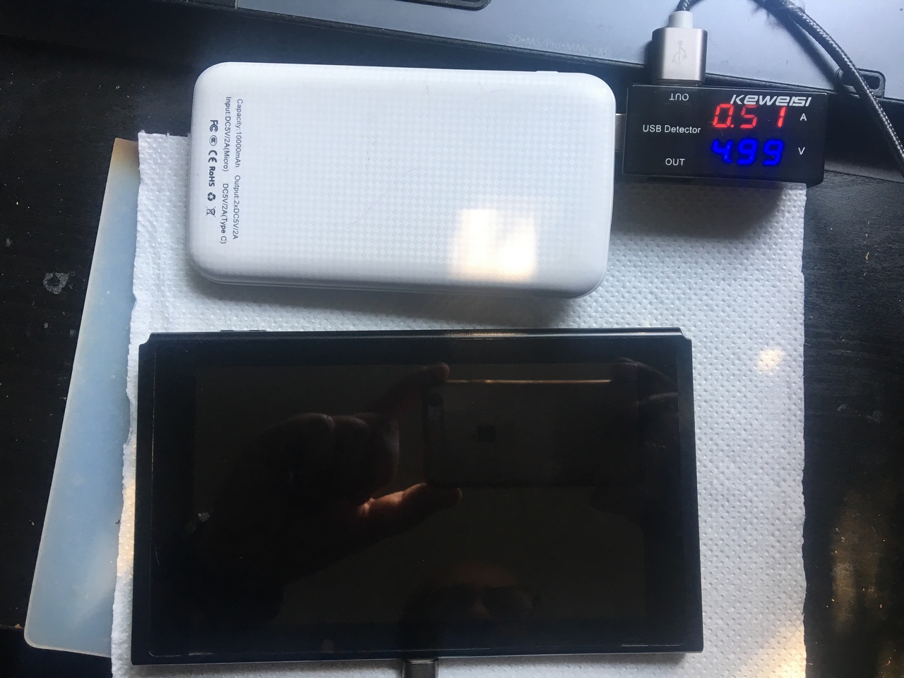
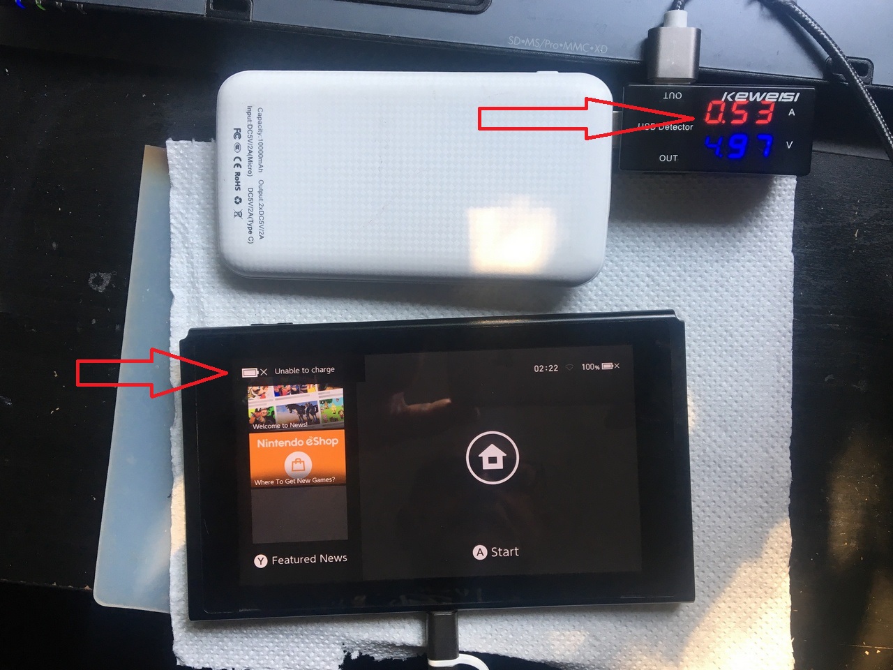
And I have another Switch that had the USB C port destroyed, I changed it with a new one, I also changed the M92T36 and BQ24193, now it starts OK, it charging in the dock without problems but if I put it on the usb cable on the laptop it tells me no can charging. It is also a series that supports hack. If I try to pass it in RCM mode, TegraRcmGUI says I am waiting for it to pass in RCM mode but it is, it does not see it through usb cable. If I put on the tester it shows me that it loads but on the display on the switch it gives me a message that it cannot charging. Any idea what to do? Sorry for my bad English.
0 charge amps usually means faulty fuse, coil or charge chip
I also changed the M92T36 and BQ24193 with some new ones. Do you have any idea where to look on the board ?
On the second Switch do you have any idea what that might be?
The usb port c is changed with a new version. Is this the problem with the second switch? In the dock it charging perfectly and send the signal on the TV. Not working with data cable and dongle…
I can’t solve the problem. In the dock it charging perfectly but on the usb C cable that neither it nor it organizes in win 7 or 10 and on the switch it appears the message that it cannot charging. I tried several cables on several laptops…
I measured with the multimeter everywhere I was advised to measure. I didn’t find anything right. The only anomaly is at the diode near the usb c port which shows me 5v on both sides although I know it has to 5v with 3v.
Hey there,
The one with 0 amps might either be the fuse or the M92T36, already had both.
The second one should also be the M92T36. The cc1 and cc2 pins of the usb cable go straight into the M92T36. These pins (among other things) help negotiate the charging current. If something goes wrong here the USB host still allows the default minimum (approx. 0,5 A) current to flow. If you measure the voltage on cc1 or cc2 (both to GND) of the USB-C connector, you should get a reading well below 0,45 V. If the voltage is well above 0,45 V the M92T36 should be ok and the problem might be something else.
And, the part labeled “1” by you right next to the USB-C port, as far as I know it is a fuse. So it is absolutely ok (actually it MUST be!) for it to have the same voltage on both sides.
Hi. Can you give me a picture to see who are The USB cable cc1 and cc2 pins? Thx
Hey there,
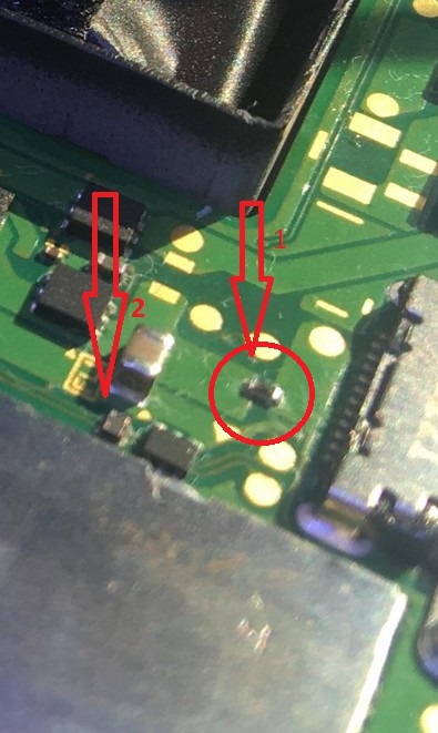
if you look at the M92T36, with the PCB oriented with the RAM/SoC shield pointed away from you, CC1 and CC2 are on the right edge of the M92T36. There sadly are not any test pads, but if you have good, fine probes on your multimeter you should be able to measure the voltage at the vias. I’ve marked them in the picture. The upper one should be CC2 and the lower one CC1. Alternatively, simply measure it on the IC’s pins.
Also, I have to correct myself. If the voltage on either CC1 or CC2, depending on the usb plug’s orientation, is well above 0,45 V the source supports fast charging. If the Switch does not fast charge, the MT92T36 might be defective. If it is well below 0,45 V, then the source simply does not support fast charging. If I understand the printing on your power bank correctly, it does only support 5 V.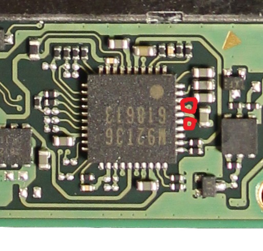
Edit: Also, did you check all caps and resistors along the path from the USB port to the MT92T36? Also, double check the fuse.
on pin 5 and 6 with the charger I have 3.5v and 3.9 v
all around I didn’t find any condenser in short.
and something else…!44.64 KΩ point 1 and on point 2 i have nothing, is dead, no value. TPD2E1B06 is removed from the motherboard. I have the same values from the pins of the USB port c
Switch charges well in dock but usb cable nothing. On the cable does not charges or transmit data…
181604-44541def88d2286b41241b01ad9845e1|471x499

Hey there,
I’ve never measured those and right now I can’t measure them, so all information is based on me looking at the datasheet.
Pin 5 (VCCIN) should be less than 6 V, that seems to be the case, that’s ok. That voltage is generated by the M92T36, it is used as internal power supply by the chip.
Pin 6 (VSVR) should be bwtween 3,1 and 5,5 V, that seems to be the case. So that looks ok.
I can’t follow your measurements. The 44,23 mOhm, 44,64 kOhm, what’s your reference signal? GND? And what do you mean when you say “nothing”? Is it zero ohms or overload (OL)? Again, what’s your reference?
Edit: What bothers me a bit is that according to the datasheet of the M92T30 VCCIN should go up to 5 V after the IC started up, not only 3.x V. But there’s not detailed description in the datasheet. I would kindly like to ask somebody to verify VCCIN on a known good Switch.
I measured the resistance to ground…
Nothing means they don’t show me anything on the multimeter
Hey there,
I never had a multimeter showing anything but the resistance or “OL” if the resistance was high, but I assume when your meter shows “nothing” it means that the resistance measured is high.
That’d mean that those points there your measured “nothing” and “nothing-dead” are actually ok. Those are the USB D+ lines. What worries me a bit is the 44,23 mOhm measurement. I’m a bit stumped that it reads 44,64 kOhms a bit further down the line. That line by the way is the D- line, which should actually be isolated from GND. So the 44,23 mOhm are definitely not ok.
Did you measure those with the USB cable connected or without it?
I measured with the usb cable disconnected
I have the same values from the pins of the USB port c
Switch charges well in dock but usb cable nothing. On the cable does not charges or transmit data…