Hi
I have a Nintendo Switch HAC-CPU-20 it charges fine but when powering on it shows th first nintendo splash screen and is then stuck on the Joycon connect screen, the animation of the joycons sliding into the Switch, and i can not get passed this screen at all.
I have tried the board in another Switch chasis with working Joycon rails and it does the same thing. I have also took diode readings from each joycon connector on the board and they look fine compared to the readings you can find on this site.
I have read on here that some people have swapped the IC labeled “PU” and this has resolved the problem, but again the diode readings of both the PU ICs appear correct from the information i have found on the is site.
any help would be appreciated.
Thanks
has anybody fixed this type of issue before
Hmmm, ok. Yes and no. Just to cover the basics, when connecting the Joycons, do neither of them show life? I don’t know much about bits in this area, but I do know the PU chips both share a common link between the middle pin on one of the sides. So maybe if both are not working, it could be something else on this line?
Thank you for replying,
Yes neither of the Joycons connect when attached to the Switch, they make the clicking sound but they are unresponsive, they are also charged and confirmed working in another Switch
Ok so the PU chips both connect to the middle pin on each of the Joycon connectors, is there any boardview available for this part?
I have checked the diode readings for the pins on each connector and thye did seem ok (no short)
Thanks
Weird. I do remember someone else saying that when they had issues with joycon detection they also saw issues up around the fan, so you could try looking in that area or disconnecting the fan?
I tried with the fan disconnected and with another fan and the problem is still there. very strange.
The diode readings from the fan, the bottom 2 pins were reading around 140 more than on the DRPhoneFix reference picture, all else was near the same.
With red probe on ground, I get 2.7v and 0.49v on the bottom two pins. Different board type though.
Thanks for your reply
on the fan connector with fan disconnected, from top to bottom i get the following reading in diode mode
.452
GND
1.902
.547
just a small update, i managed to get the right joycon to connect, but the left one will still not connect
Nice, what did you do to get the right one working?
nothing really, just sat there for 10-15mins trying to pair lol,
im sure the left one is due to a board fault, i tried another joycon rail and still didnt pair
Easy repair. Most likely you have a bad diode near the fan. Check it for short and done deal. $99 repair. If you check the diode and no short reply to me for next step.
Game Guys - Houston
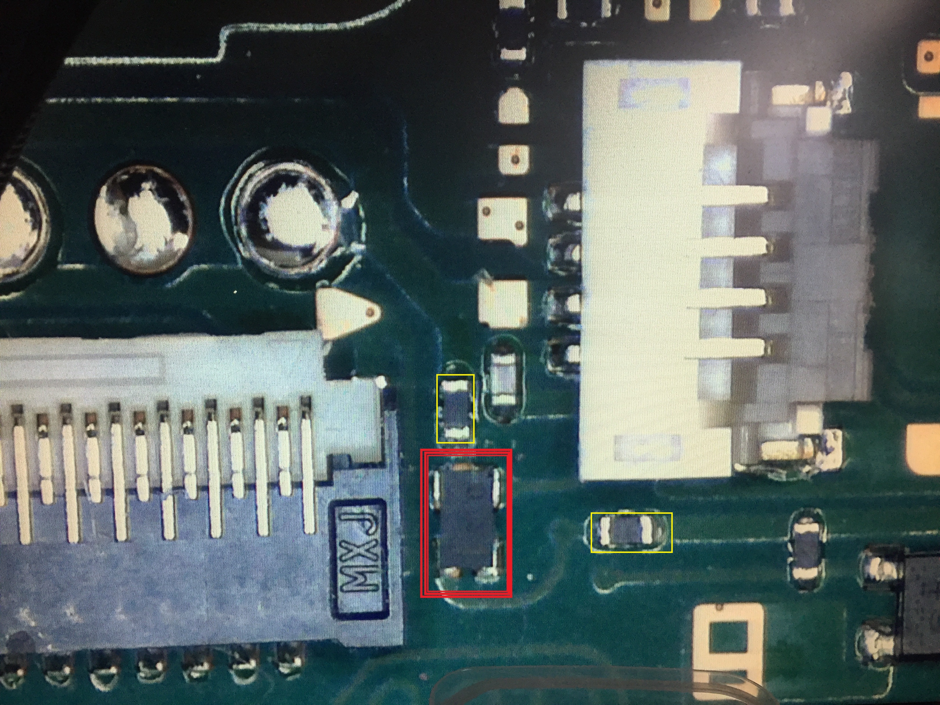
thanks for the help GameGuys, do you mean the component highlighted in red in the picture? is it a diode, it looks as if it is a dual component, different to the other diodes on the board.
Hmm, everything else in that area doesnt much look like a diode either. When I measure between the top and bottom (from the resistors, as its too tight for the probes), I get different values in each direction, but its not OL and ~0. That may be just because it is in circuit though.
What values do you get across it?
Do you mean the two resistors highlighted in yellow?
Yeah, I was measuring from the inner side of those, as they seem to be the obvious parts that are connected to it.
ok, in diode mode, red probe on gnd im getting .434 on the top one and .667 on the bottom one
.444 and .708 here, though different meters so would expect some difference… hrmmm
yes im sure thats close enough to be good