Look it over, also noticed the 1v3 rail previously tested in the Mohms but now its in Kohms.
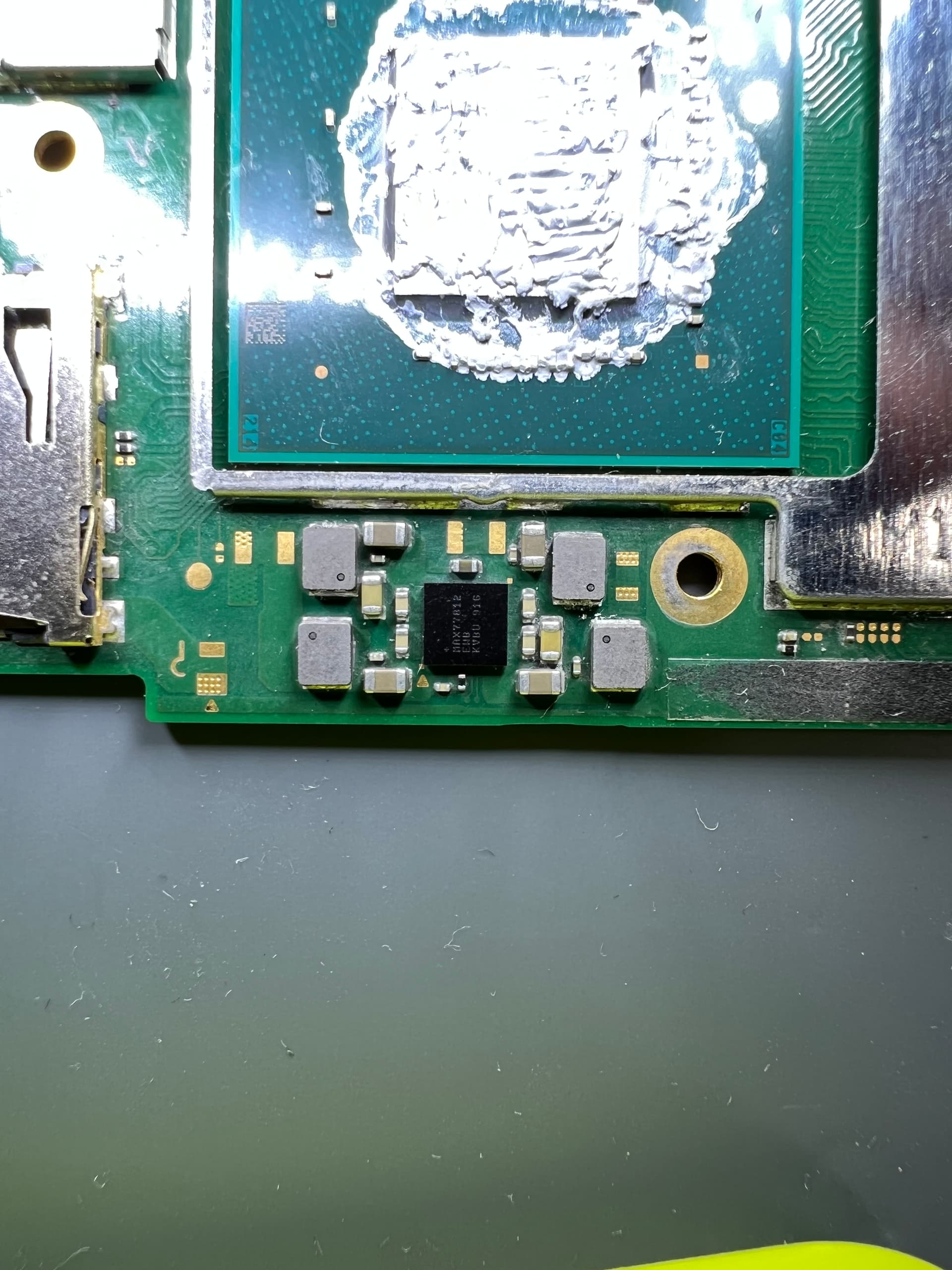
Would indicate it is actually booting ordinarily. Check over at the other Max IC (below SoC) at the inductors and see if your getting main CPU Rail and/or GPU rails showing up to verify this following prompting the console to boot. If you do then your not dealing with a power-on issue but more likely a display / BL related issue.
If you don’t get these rails present folowing prompt to boot then I suppose it’s possible you’ve inadvertantly (and this is a complete guess without looking at the board myself) dislodged Ram during rework of the USB port… though with this being a lite board the Ram modules are a bit further away so possibly more likely would be the Wifi IC becomeing dislodged or possibly the fuel gauge. All guesses mind you with knowing more. - and to note: by dislodged I mean either warping of the board leading to IC’s not making proper contact with the board anymore or chips have moved or solder smeared during work elsewhere.
I have a feeling (and if I’m remembering right) that on Mariko/Lites that boot CPU rail voltage drops following bootloader stage (ie: after the console has booted into the OS) which makes sense given that the boot CPU isn’t used following intial boot. So measure the voltage while prompting to boot, if it’s approx 1V ish during boot and then drops down to 0.6V after a few seconds/minutes then I’d deem this normal behaviour.
Stop randomly reflowing, removing, repacing etc things… you just muddy the waters by doing this.![]()
Don’t worry about this. Pretty much any in circuit measurment is not a fixed/static thing
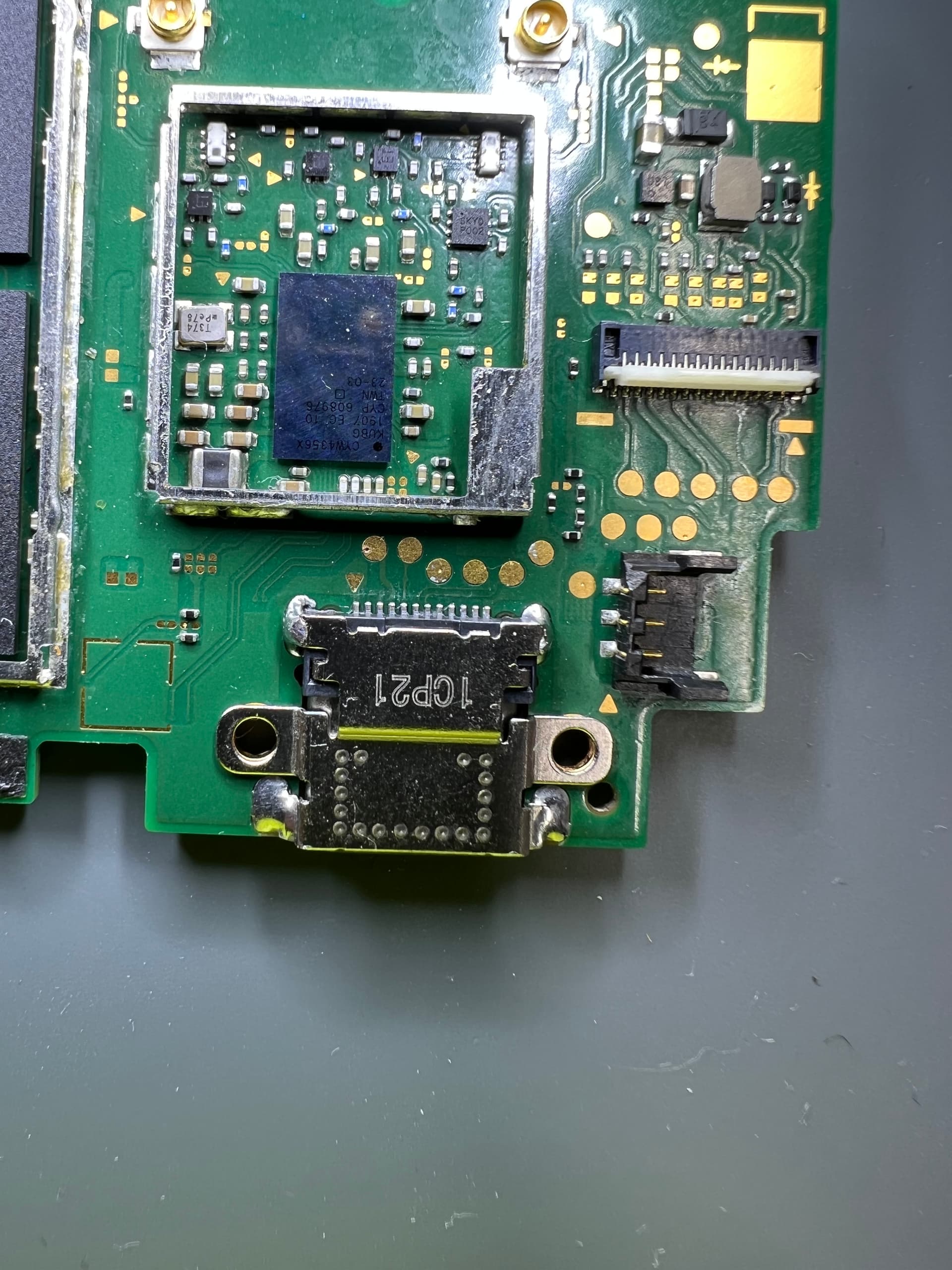
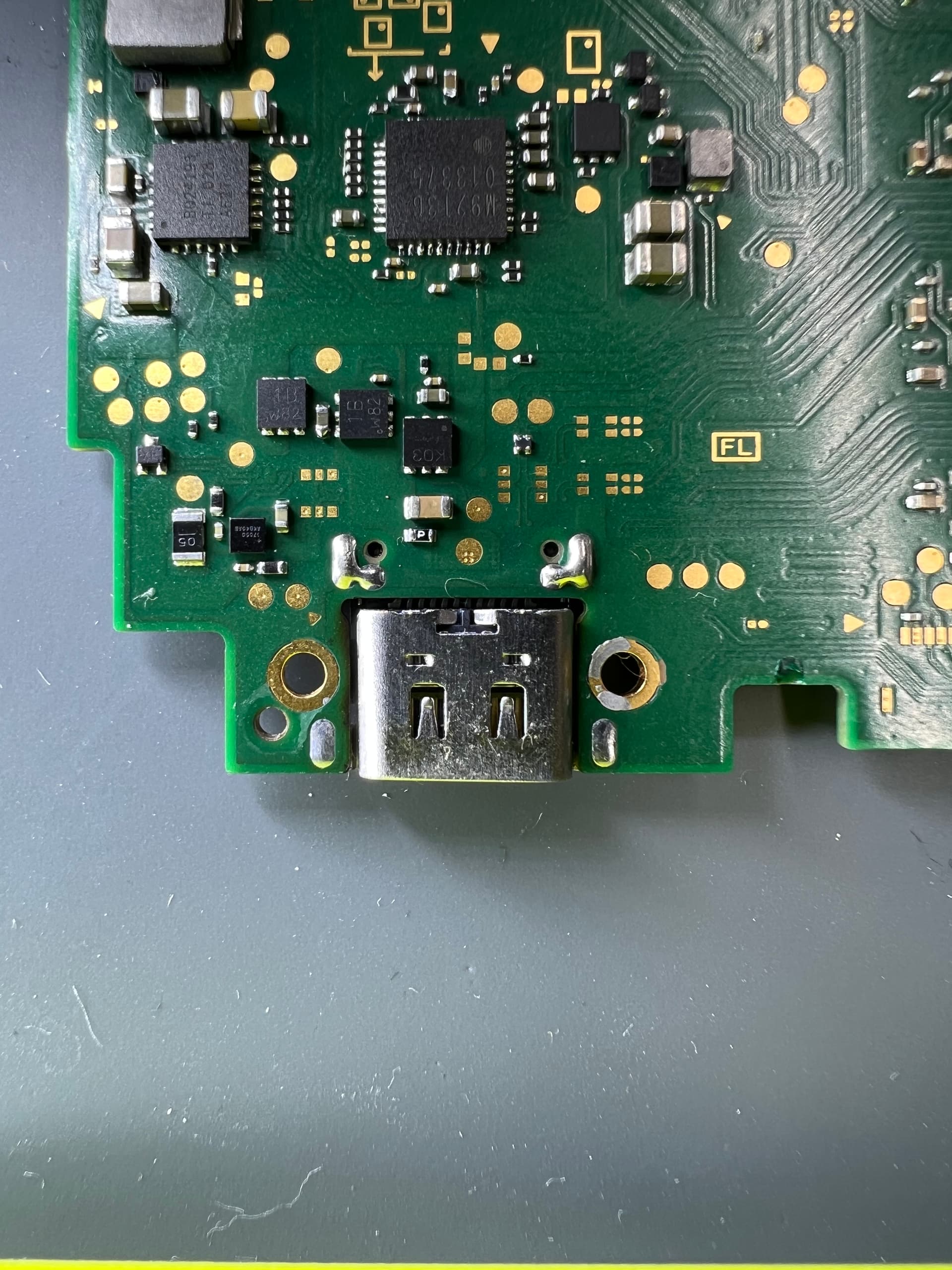
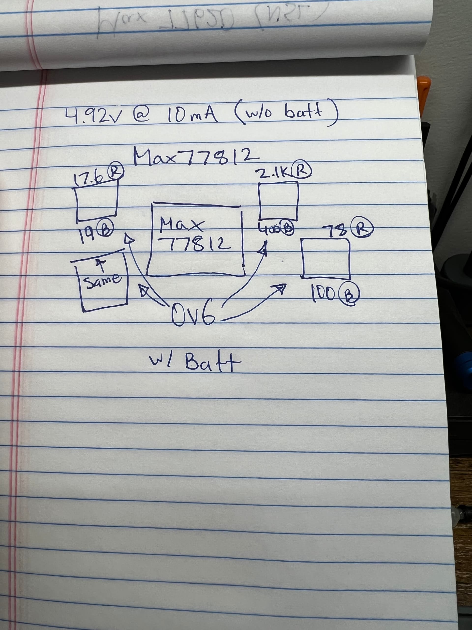
If you have the NSL working before USB port replace, most likely msx17050 got mess up by accident. What current draw without battery? What voltage around Max 77812 when trying boot up ?
i want to second this, the fuel gauge is highly susceptible to wonkiness when changing usb port on a lite board. Id look here first and inspect the solder balls and make sure none have merged or squished out on ya.
The switch is fixed. Took all of your advice to my board and everything tested fine. (comparing to values found on this forum). I knew it most likely couldn’t be 17050 because I am always super careful with my heat and pre-heat the board with my hot air before focusing on a specific area plus the balls looked fine. The culprit turned out to be the main flex ribbon. I did a visual inspection several times before but never checked for continuity and when I did a few of the lines weren’t beeping. Pulled it out and it was badly kinked/pinched by the speaker area. Considering how many times I handled this device, I must have pressed on the speaker too hard but to be honest the way they designed and positioned this flex is horrific. Right by the speaker is a corner of the aluminum sub-frame which is asking for damage. I pulled the same flex from a junk donor switch I have, and it too had signs of wear in that same area.
@Severence I reflowed 17050 before you advised my temptations ![]()
Thank you guys for all your info, it was all written down, and saved for my future use so your time wasn’t wasted ![]()
1 Like
Yeah, had a feeling it would be something along these lines. Glad you managed to resolve the issue, nice work ![]()
Also, just an observation - your soldering work at the M92 looks a little chunky, this is typically as a result of soldering iron not being hot enough and/or not enough flux and/or the wrong choice of tip, you should ideally see nice fillets which are completely smooth all the way round - if the cause is the soldering iron (not being hot enough) try bringing your hot air in to assist at approx 150C low to med air and see if that aids you whilst using the soldering iron. In this case, as everything works might be best to just leave it be and apply this to future repairs ![]()
@severence Good eye and yes it was the wrong tip. That’s why there is extra solder on nearby components. I have an Auxin T2A station and working on this device I realized it’s time for some proper-sized genuine JBC tips which have all arrived except for one, the smallest and probably most important one, lol. What about the port change, good? All plastic in tack and nothing melted ![]()
Side note, wow how good it is working with good tips. If anyone is using an Auxin or similar device with the provided tips, do yourself a favor and get some genuine tips. They are pricey but it is so worth it. Plus you have a much bigger selection of sizes/styles compared to the 5-6 offered from china. My only issue is that the overshot using genuine tips is 30 degrees over compared to the tips provided so I am trying to figure out how I can calibrate my station without one of those temp devices. For now, I just give it an extra second or two for the temp to drop before I apply.
I wasn’t sure if I should make a new thread but I also ordered those rubber plugs for the T245 handpiece and they are only sold in a pack of 10 so I have 9 that are collecting dust. If anyone needs one, let me know and I’ll mail you one for free. My tiny contribution to the board ![]()
Wouldn’t worry too much as the smaller the tip the worse the performance, you can do 99% of all work (even fine pitch work) with a massive chisel tip and get superior results (with practice) - I suppose the smallest tips I often use would be the J type style tips but tbh more often than not I’m using the much higher mass heel portion of the tip
Yep looks good to me afaict - just check that with a battery at <80% your getting charging currents of greater than 0.8A (as I noticed this was a little lower in the prior post) if your not seeing that, then can often just be as simple as a fluxed up USB connecter (and/or cable) which either an ultrasonic will resolve or if you don’t have one- contact cleaner and a clean toothbrush. IPA on it’s own doesn’t make for the best flux cleaner in the world… atleast not without heat aid. If the current still fails to increase beyond that it might indicate a floating pin (or two) on the USB connector.
I’ve got this unit, though it’s not my daily station… just bought it out of curiosity. I got the T12 handle version, can’t say I’m particulary fond of the style of handle they use as the tip stickout is far greater as compared to my main T12 station but I’d still rate the T12 tips much higher as compared to JBC style tips (in contrast to a lot of other people) - I’ve found the official JBC 245 tips last the same or significantly less time as compared with the particular “clone” of tips I got, for example I used a JBC handle for a few weeks to get a feel for it, in testing I used a J style tip (don’t remember what JBC refer to this style as off the top of my head) and after this period the tip had pretty much worn out and solder would no longer take to it… Performance in general started out good, I’d say even slightly better as compared to T12 tips but as the days wore on the performance degraded and I had to switch back to T12… Of course, this all depends on which tips your using with your T12 handle/station mind, generic clone tips from Aliexpress are hit or miss, sometime they’re great and sometimes the exhibit the same beahviour as the JBC tips (albeit at $3 per tip vs JBC’s $30 or so) I’ve found the Mechanic brand of T12 tips to be of surprisingly good quality and the coating seems to last really well… which is a surprise considering this company largely makes complete junk, so I guess these are a rebadge of some other manifacturer.
You can buy a clone Hakko tip calibrator from a variety of places for extremely cheap and they work pretty much as well as the genuine… though tbh with this T2A station it’s largely pointless as there is so much variation in temp calibration beteween tips that the moment you switch tip you going to throw your cal off by upwards of 70C (depending on how long the tips have been in use and wear etc) . This is the reason why I don’t use this T2A station as my daily driver as I like to have cal profiles per tip.
Good to know. Ill keep an eye on the current.
Hmm that’s disappointing to hear considering all over their website they state how they are long-lasting tips. I guess I got hyped by the immediate performance difference but I haven’t used the genuine tips long enough to make comparisons. I didn’t get super tiny tips but something that would at least get in there because the tips I had, wouldn’t even reach the pads. How long does a tip usually last? I know it depends on usage/care but to get a ballpark. Are tips replaced once a month or once every 10 years?
Makes sense on the calibrator. I did notice that with the 5 JBC tips I have, they all overshot the same. I have my pre-set at 330C and once turned on, all the JBC tips jump to 370 while the clones jump to 350C. Are there any risks I am not seeing with the overshot?
Yeah it’s all marketing wank I’m afraid… Unfortunately the average Joes reviewing these tips JBC tips and the clone JBC tips also get caught up in it too (at least as far as I’m concerned based on what I think is unbaised testing of both styles of handles/tips)
Like you say it really depends on how often your use it but also the set temperature, for example I’ve found prolonged use of genuine or clone JBC tips or even T12 tips at temps of 420C or greater for prolonged periods (IE: this is your default temp) can destroy these tips coatings in short order, potentially in a few months, wheras maintaining 380C or lower doesn’t but other factors such as your tip cleaning method can play a part… people who use water on sponges will likely see quicker degredation of tips but also people who use “brass sponges” aggressively can too (note: pretty much all of these so called brass sponges are infact brass plated steel wool and as such will wear and ultimately start to damage all tips to some degree as time wears on) - Calibration can also play a part, depending, for example you set your tip to 380C but in actuality it’s operating at 440C unbeknownst to you. The use of low melt alloys damages tips so it’s highly advised you have a dedicated tip for these if you plan on using them… also avoid those “tip rejuvenators” or “tip tinners” which are effectively just a low melt alloy solder paste (much the same or similar to conventional low melt solders) which will have a temporary effect of making your tip more readily acceot solder but will significantly decrease the long term life of the tip in actuality. In general excluding all the problems above, and assuming a good quality tip with no coating defects, and let’s say the tip is used a couple of times a day for 30mins, then I don’t see why the tip shouldn’t last upwards of a year or maybe more, especially if your cycling between different tips in use… If you using the tip every other week then perhaps upto a decade is possible… I know I have like somewhere in the region of 20+ T12 tips from back when I got my T12 station probably over 10 years ago which are all still good (and that’s with heavy use) all are clone generic T12 tips… though as I mentioned earlier the quality of these generic clone tips is a coin flip as to the actual quality and in turn longevity (afaict the quality does seems to be getting worse these days based on a handful of random generic tips I’ve recently ordered and tested.
Some tips on determining whether you’ve got a good tip ![]() look at it under the microscope, if you see striations, dings, bends, chips or machinest marks on the tip coating, then it’s a pretty decent indication that the quality of the tip isn’t the best (not to say they’re unusable but just not the best) if the tip coating is smooth, shiny and you can barely see any machist marks or straiations then it’s a good indicator the tip was well made and probably has a good tip coating on it and will probably last for a good while
look at it under the microscope, if you see striations, dings, bends, chips or machinest marks on the tip coating, then it’s a pretty decent indication that the quality of the tip isn’t the best (not to say they’re unusable but just not the best) if the tip coating is smooth, shiny and you can barely see any machist marks or straiations then it’s a good indicator the tip was well made and probably has a good tip coating on it and will probably last for a good while
Play it by ear. if the tip is refusing to take solder and it’s just dropping off then it’s due for the bin. What happened with that JBC tip and what tends to happen with the crappy T12 tips is after a few weeks solder will stop taking where you want it, then you’ll compensate by using the area of the tip which does take solder where you don’t want it ![]() then it won’t take solder at all, at which point you chuck it out
then it won’t take solder at all, at which point you chuck it out
While calibration can have some impact on this, overshoot is more down to the PID routine of the station, this can be good/bad based on the combination of tip to station (for example deviations of TC bahaviour inside the tip, and also the elment resistance etc) but it can also be bcause the station just doesn’t have a very good PID routine in software (which is more common) As I say i don’t really use the T2A station often but from what I remember the routine is meh… the LCD makes it look swish and fancy but the routine is pretty basic, but it works and the station is overall decent
It will be fine, though it does indicate that their stations PID routine is better tuned to the clone tips (at least this particular type of clone) as oppsed to genuine tips. I suppose it if your set at a high temp let’s say 400C or more and your repatedly taking the iron out of the cradle/standy over and over it could potentially shorten the life of the tip as it overshoots over time, though I think in reality the effects would be pretty negligable for the average person.
All great advice. I am looking forward to seeing how well/long these genuine tips will last but I do always practice good tip habits. Always apply solder on the tip when Im done working and aside from the overshot, my temp is always set to 330C. For now, I am very happy with the station, maybe because I have never used a better one or maybe because my first station was a very cheap iron and hot air combo from amazon.