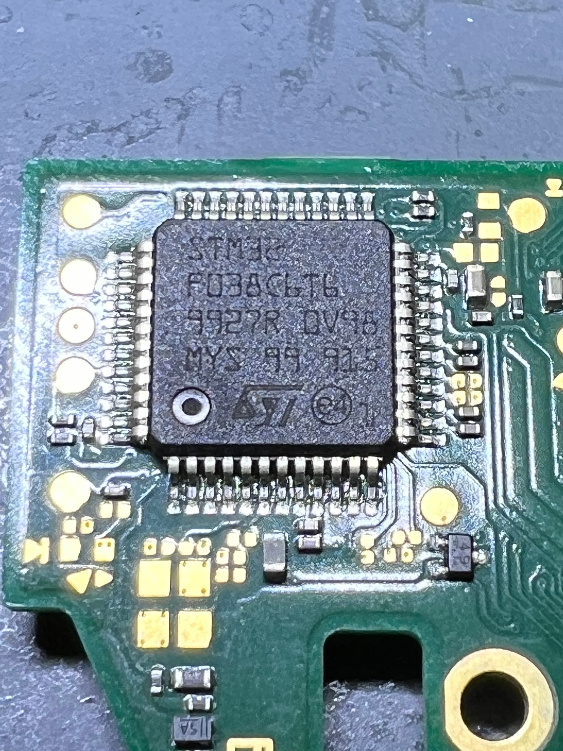
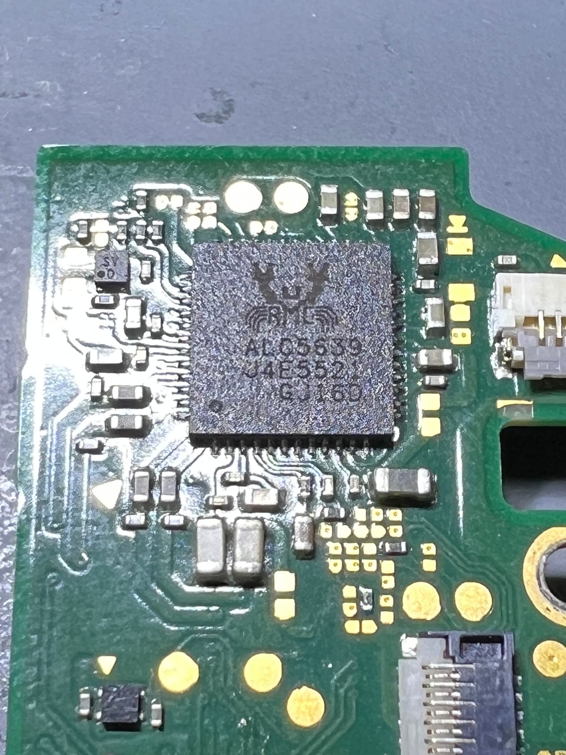
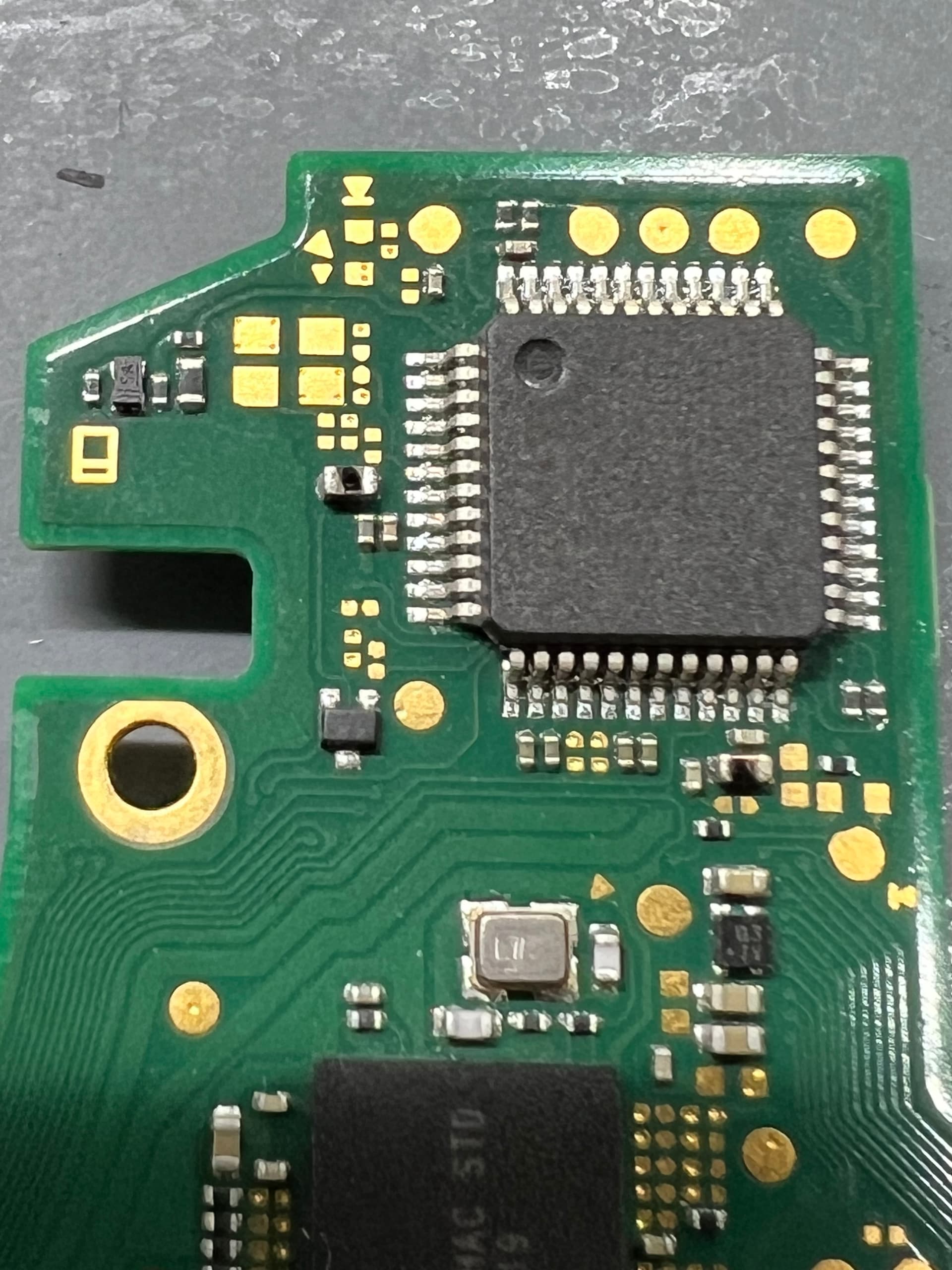
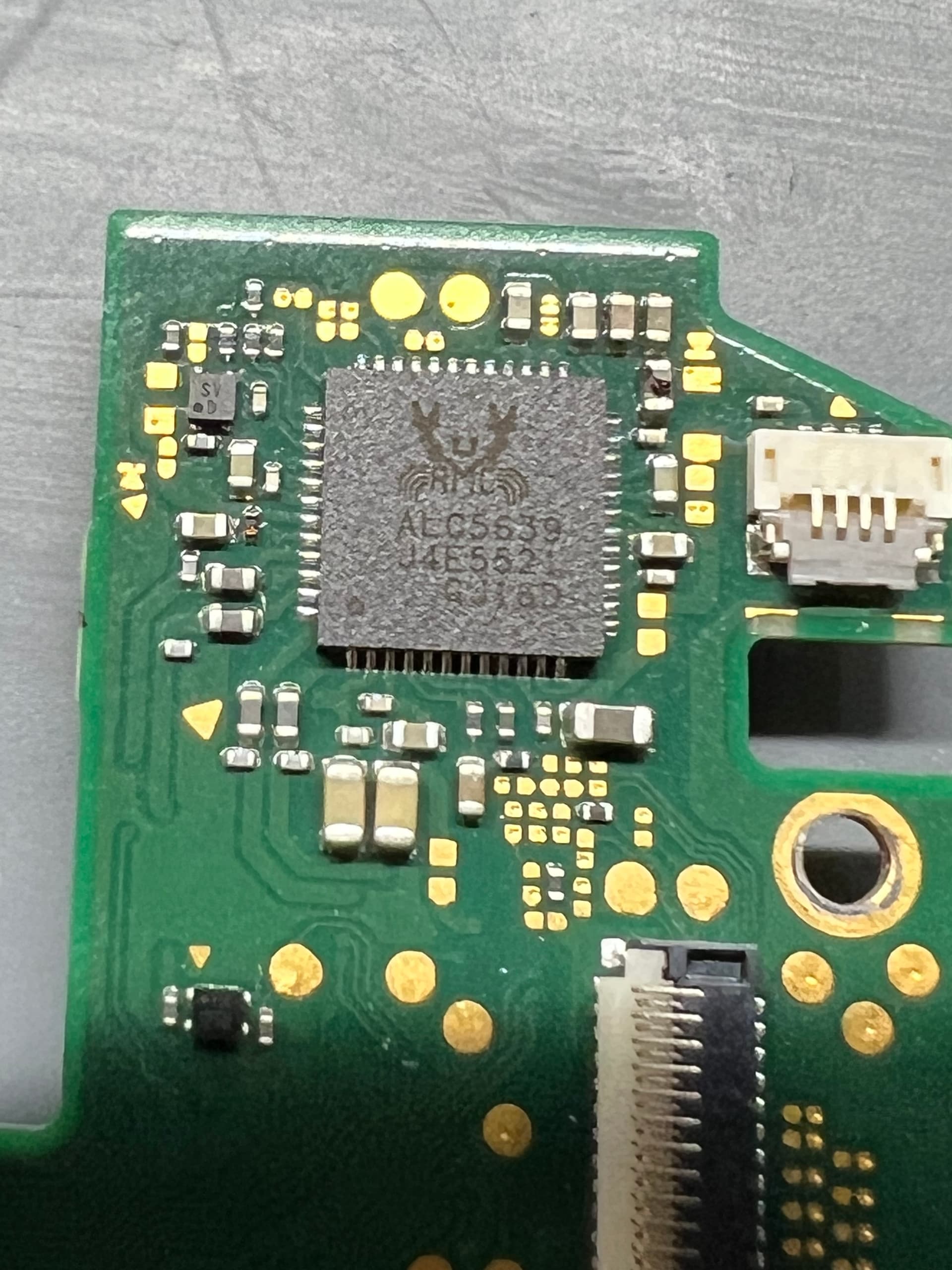
I’m new to electronics and repair but love each and every step, moment, and repair. The switch in question is my son’s that I have done work on before (charge port) and have learned on. Last it wasn’t turning on, found a short on M92 and replaced it. Works fine but the next morning battery went from 100% to 20%. Charged it again and turned the console off. Came home and it’s dead. Took the board out again and see no shorts on BQ or Max17050 but did notice 2 big chips getting warm to the touch. I can’t see how to add pictures but the writing is: STM3 F038c6t6 9927R 0V98 MYS 99 916 and the other RMC AL05839 J4e5521) They are on opposite sides of each other so I can’t really tell which is getting hotter but I get 2 shorted caps (at least what I believe to be a cap) on each side. I will try freeze spray today and see if I can isolate anything. Also, the board draws 0.20 @5v with or without a battery.
PS I have tried various other forums in the electronics community and maybe it’s my questions but I am beginning to get the feeling that newbs are not welcome. I really hope I can find a home here to learn and grow.
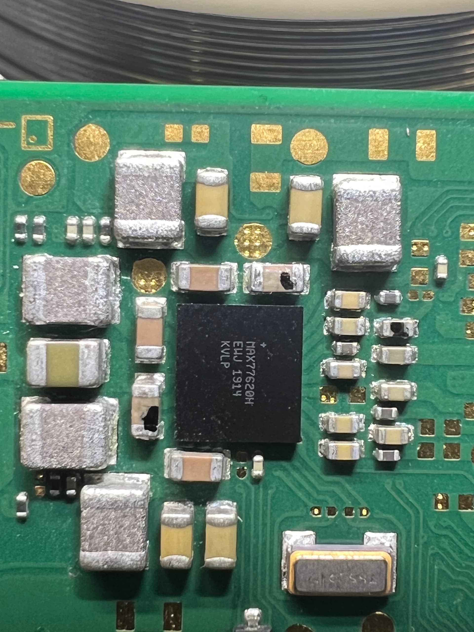
Figured out how to upload pictures. I marked the shorter components with a black sharpie so hopefully you can see the black dots. There are only 2 on each picture.
The top IC is the chip responsible for handling button input, IC on the bottom pic is the audio chip. I do believe the capacitor on the right in the top pic you have marked is tied in directly to the audio chip. Have you removed them to see if the shorts clear?
No, I haven’t touched them. I discovered them heating up when I was already calling it a night and snapped some quick pics and took a few measurements. Figured this would be a good intro topic for me to jump in since I haven’t seen these ICs mentioned in any thread here or in other forums. But you are right and I forgot to mention this, the buttons are also not working.
Ok, I have a donor board and will swap them out one by one and check for shorts.
no problem, i would start with the STM chip first as it is a lot easier to remove and replace than the QFN audio chip. Ive had to replace a few of them myself, its definitely not a common fault for sure.
Coda, thinking more about you saying this is an uncommon fault I decided to check Max77620 and found 3 shorts. 2 of those shorted caps look bulged. I will go back and read all the threads about this IC but wanted to add this to the thread. I did not yet touch the microcontroller or audio IC. Think I need to address Max first.
MAX77620 is integral to the switch as a PMIC. From my understanding though, it is a very sturdy chip and doesn’t often suffer random failures. Most times when this chip fails its due to liquid damage / corrosion or impact damage breaking a ball underneath. As it is a BGA chip I wouldn’t mess with it unless you have preballed replacements on hand, or if you are experienced and comfortable with reballing.
You should see your main voltage lines on the surrounding inductors on this chip, there are a bunch of threads on here though that will show you the expected voltages / resistances / diode readings for this area. Double check the resistance readings on these passives, it is entirely possible you have a high short condition which causes the meter to buzz but is not a dead short to ground. Most likely your fault lies somewhere upstream of this chip and is just dragging those passives low enough to cause the beep. Regardless, I wouldn’t remove that MAX IC until you have exhausted all other options
I don’t think your issue is related to this IC, but it very may well be in the end. Just probe around and compare your readings to known good values.
A little update on my board. I confirmed the board was drawing around 0.135amp and isolated that the heat was coming from the audio codec which I replaced. Board is now not drawing any current but when I try to turn it on, I get a Nintendo logo and the screen goes black. When I plug the charge same thing, the battery charge logo comes up and the screen goes black. I made sure to check all of the fps connectors for any bent pins and also made sure to very carefully put the flex cables back in for testing. I’ll have some time tonight to check the board again as well as take some measurements to compare to known good values.
I get so much information, taking screenshots, taking notes that when I sit down to actually do something I feel so lost and overwhelmed.
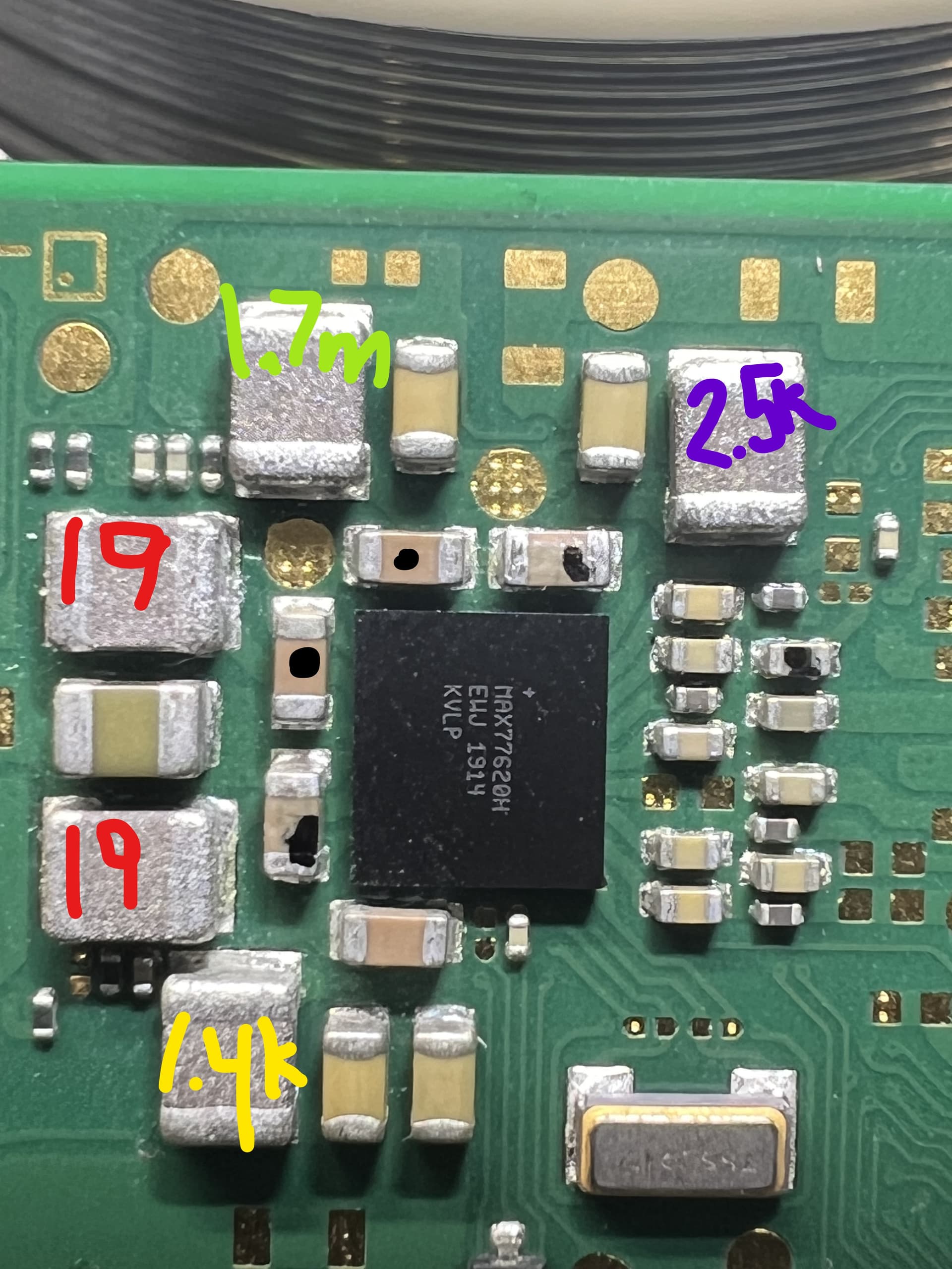
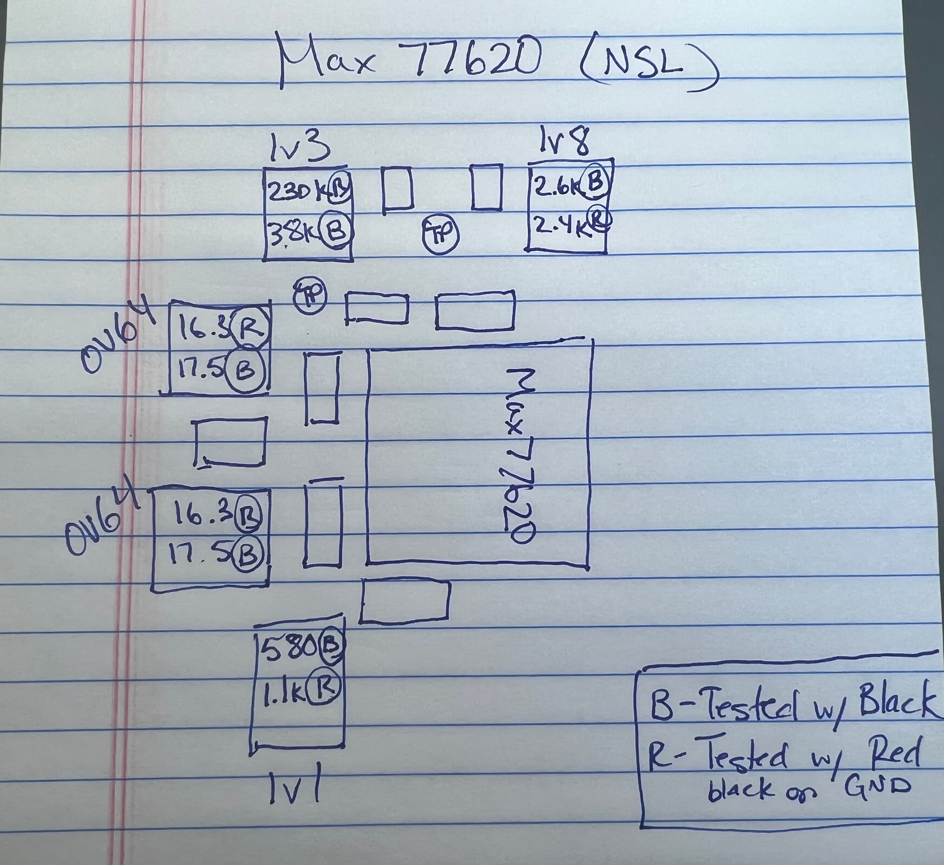
So the shorts I had before round the microcontroller and audio codec are gone but now the 4 caps around max are all shorted when before only 2 were. I took resistance to ground measurements as pictured and made sure to triple test each spot. I compared my testing to tests posted on this board of good boards and the purple and red inductors are too low. Purple should be 33k and red around 50. I dont have a good board so test myself so replying on someone else’s testing.
There are no limitations in terms of swapping ICs as long as its the same exact IC right? I know there are a few variations of the switch lite board and I am taking my ICs from what I believe is an older version or at least its different than the board I am trying to fix.
Slow down mate, your PMIC readings seem about right afair for a Lite board (I guess you comparing the readings to an original revision) I’ll pop back in a bit and help you further. In the meantime search the forum a bit as (as has been mentioned) these rails etc and measurments have all been covered quite a few times.
If you can provide readings - resistance relative to ground on the caps near the audio IC which you suspect are shorted/on a shorted line, that would be good
I’m just very excited to be able to speak with someone. Reading books/threads and watching videos has been extremely helpful but up to a point. I’m really trying to learn and even paid for a class (huge waste of time and money). I have 2 full notes books of notes I took watching various videos so I’m not lazy to do the work, I’m just lost and have no one to turn to and not just with this switch but in my electronics learning journey. Feel like I am missing a piece or two of the puzzle to have that “ohhhh now I get it” moment.
Before I made this thread, I conducted what I believe to be a good search on this forum about my topic and switches in general, and have lots of helpful information. Took about 30-40 screenshots :). I even went on your and Coda’s page going down the lengthy list of replies you guys have posted looking for something helpful. So either I missed it or am overcomplicating the issue, or lost lol.
Sorry for the rant and thanks for your time. I’ll get the resistance reading around the audio IC and microcontroller.
Hey no worries man, happy to help. Just to note though, I have been through this exact same conversation with people like 50+ times so I really would just be repeating myself tbh - that includes your symptoms and your assumption of what could be potentially wrong (the assumption that you have those shorts around the PMIC etc) So it’s denfinately worth trawling through the forum looking for these posts as a lot of what I say is stuck on repeat
Hey no worries, unfortunately I don’t think there are general moderators here otherwise I’d have asked them to sticky a few of my posts/topics a long while ago so I can redirect people.
So I’m guessing the initial points around the PMIC which you orginally thought were shorted were the boot CPU rail (these are the inductors you’ve labeled in red) which is commonly thought to be short which actually arent’(search for something like “my CPU is short”) for common threads on this topic which will delve into more details regarding that.
Your rail in purple is your 1V8PDR, it’s a touch low in my book, but it’s pretty typical depending on your meter to get a reading somewhere along these lines… if I recall on my meter on Lite boards I’ll measure (i think) about 5K (depending on probe polarity). Everything else looks fine as far as I can tell around your PMIC… If you find you consistently get a drastically different reading on a known good Lite board (or Mariko revision standard board) report back and we can possibly drill down on this… 1V8PDR (this is another key search term ) goes pretty much everywhere on the board so something else could potentially be pulling this down if that’s the case.
The caps you’ve put the dots on. I don’t think they’re a problem, might just be baked on flux or manufacturing defect
No worries I know at times it can be frustrating knowing which steps to take, but your making all the right ones so far. Just resist the urge to start pulling things off the board without proper cause to do so
Hey guys, first let me give you guys a big thank you for your time and advice. The switch is working just fine, charges and buttons are working and I did not notice any battery drain issue. I’ll get into how below if you want to skip the lessons I have learned.
Reading lots of threads, I now have a much better under of the beginners. It’s actually funny and sad at the same time and I can see why it can be frustrating at times but you guys are goats. Won’t get into specifics as I am not here to cause trouble but I get it.
I also understand the importance of looking up datasheets and trying to understand the IC and its purpose.
Pictures are another thing, although I have a trinocular microscope, I never got a camera as I am not planning on making videos and don’t really need the image on a screen but I didn’t think about pictures. The pictures I posted seemed fine using my phone but after I went back and looked, it’s a mess up close. If anyone has any suggestions or can tell me how I can use my iPhone to take pictures with my microscope that would be great. I tried one of the eyepieces but with 3 cameras (Iphone 13 pro max), it keeps jumping and trying to refocus itself. Buying a camera is on the list after a new better hot air station.
Again thank you very much. I think I have found a home :). I also ordered 2 more switches from eBay, scary buying from there as it seems everything is someone’s junk. Try to fix it, break it more, and list it on ebay.
Now on to the resolution of this switch. After reading more threads I decided to start all over. Check the usbc port and found a broken pin. Then looked at M92 and found that I placed it off-center giving the potential of shorts. BQ was looking fine and the microcontroller was too, but the audio IC was also a bit off. Fix those and the board started to draw normal current. Connected everything to check and things are working. So my understanding is that the microcontroller was to blame for the battery drain and buttons not working and my poor work on M92 was the reason it wouldn’t start. I could be wrong but after replacing M92 it powered on and charged. Perhaps it worked fine until some debris got near M92 and caused some trouble. I also learned that I need to check thoroughly before ruling something out and double-check my own work.
Sorry for the long post but this thread will be marked resolved. Not a ground-breaking resolution but can surely serve a purpose for someone.
What might be worth checking (and also so you know for furture reference) is measuring the resistance to ground on your 1V8PDR again and seeing if the values return to the expected now since your fix. If it does then it’s possible that this rail (which shows up at the M92 IC) was bridged with some other I/O thus pulling the rail down.
Also in regards to the camera stuff, I wouldn’t personally bother investing in a dedicated camera. I can take digital microscope grade photos of a board with an old iphone 6 and they look fine. Half the battle is lighting, try taking your photos under your microscopes light with the HDR mode off. don’t hold your phones camera too close to the board … iPhones are terrible at being able to focus (at all) when held to close to the object, I think the minimum is approx 15CM away from the object. If your still having trouble with the focus, try some of the third party camera apps out, I believe some allow you to disable the somewhat annoying default behaviour of auto focusing (which it’s terrible at unless there is a face involved)
Learning the lesson a lot of us have been through, and continue to go through I know I personally struggle with QFN chips a lot, so if I have to replace one I know by now to go over all the “legs” with a fine tooth comb and look for mistakes.
I’ll also agree with severance here and not that a dedicated microscope camera is not necessary unless you plan on recording your work.
Something like the above may be beneficial to you and using a smart phone if that is the route you want to go. Using any type of high zoom almost always requires a tripod / stand of some sort unless you are one of those superhumans with steadycam hands.
Removed the “solution” as I am with this switch again. This thing is holding up my other projects and is starting to feel like kryptonite. My son gave it back to me saying the R button wasn’t working. Took the board out and yes that button was smashed which I replaced and figured since I already have the board, I’ll change the USB port. Did those successfully and now it won’t turn on. Check all of the FPC connectors and the flex cables which are fine. Charging also seems to be fine 5v 0.70amps however I am sort of missing voltage. I have a rail that should be 1v0 but it’s 0v6 instead. I uploaded a picture showing the voltages and resistance to ground with both polarities. I am not sure where that rail goes to or what my next steps to find it would be. Also a reminder, I never changed 17050 but reflowed it. I already spent 3 or so hours sitting testing, looking, reading, and trying to figure out what could be wrong. All I did was replace the port with a brand-new one.
@coda Funny enough I actually have something like that. When I just started, I was planning to use my phone as a microscope and quickly learned what a fail that was lol. Thinking about it now seems to funny. I tried Severenace’s tip and used my microscope light with my phone and it turned out a lot better. Still need some practice to fine-tune it but that will work.