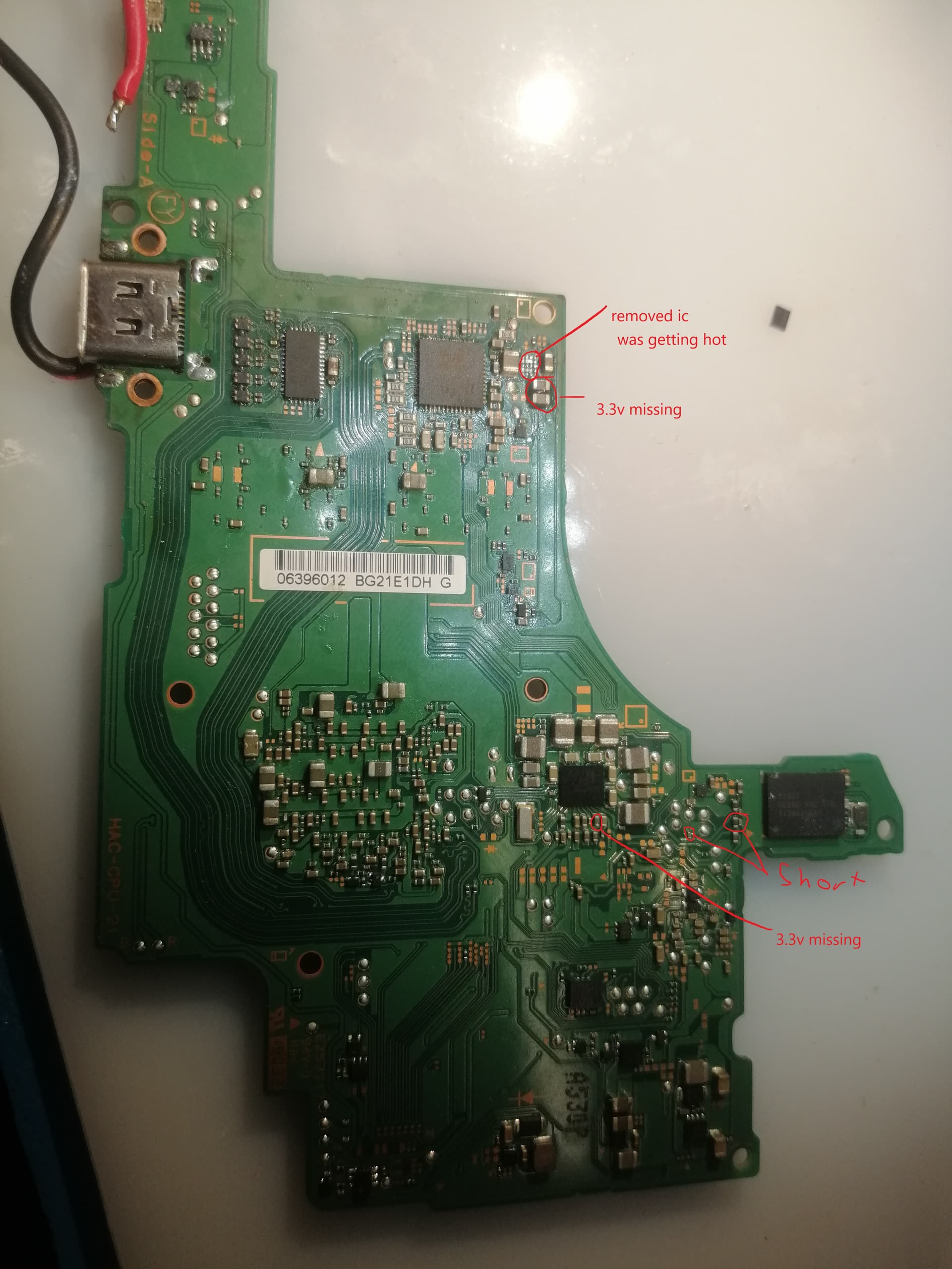
Hello, i have a switch that just had a bad battery. i replaced it and charged it from my 5v psu, no problem, when i plugged in the oem charger it turned of and wouldnt turn back on i think my charger might be faulty. after that, 0.2a at 5v at usbc and 0.46a when pressing power button but no sign of life. i opened it back up and now have a short next to m92 with another 2 on the back of the board. when powering the 4.2 line with psu it draws 300ma looking at the thermal camera the engx/enev chip was getting slightly hot (40 degres at 30deg ambient) i removed m92, short stil present, i removed engx short still present, power draw down to 200ma as usual, with no heat visible. max77620a (the one on the back) has all volatges present except the 3.3 line, never had this issue, i dont even know what produces the 3.3v but i guess its enev. i solderd a on the same part from another board i had lying around same problem (300ma with +10 deg thermal) allthough one is labled engx and one enev (guess theyre the same?!?), at this poit i dont know witch one was the original but the fault is present with both of them. im dying over here this bitch only had a broken battery and i fucked it somehow ![]()
removed emmc no difference
the part you have highlighted is responsible for the 3.3v line, so yeah if you pulled it (and m92) and still have a short something else is bad on that line. The audio IC (the big IC right under the ENxx you pulled) is also tied into the 3.3v rail. Maybe take a quick poke around the southern caps and consider giving the IC a pull if you’re up for it. Ive had it go bad on me on a few and prevent boot, its not a common fault though so I would not expect it to solve your issue.
I am assuming you also pulled the caps around EN and M92 to verify they weren’t the problem? There are times when the caps themselves go bad and just need to be replaced. Just pull them out of circuit (and leave em soldered to ground) one by one and test to see if the short goes with it.
Looks to me like the PI3 has been messed around with… I’d probably be starting in this area given it’s on this rail. Failing that, put your meter in resistance and go to all areas where the rail shows up and see which area represents the lowest reading to narrow it down.
Always concerns me somewhat when i see people soldering their ground leads directly ontop of the USB port as it’s usually a good indication of bad things.
With the voltage limited to 4.2V though right? if no, you can’t do that.
WHY not inject voltage from your 3.3v short line ?
i have a variable powers supply dont worry haha
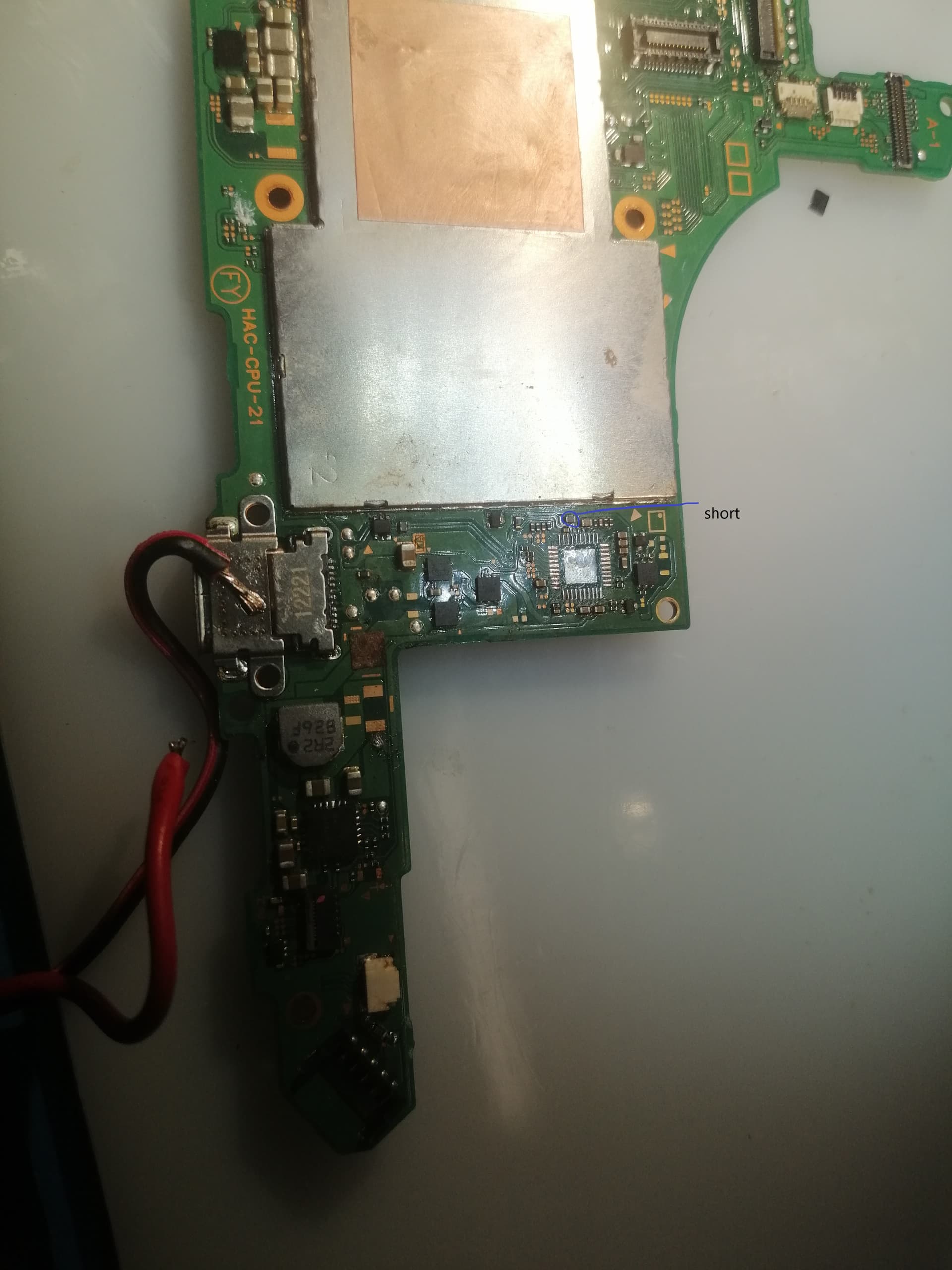
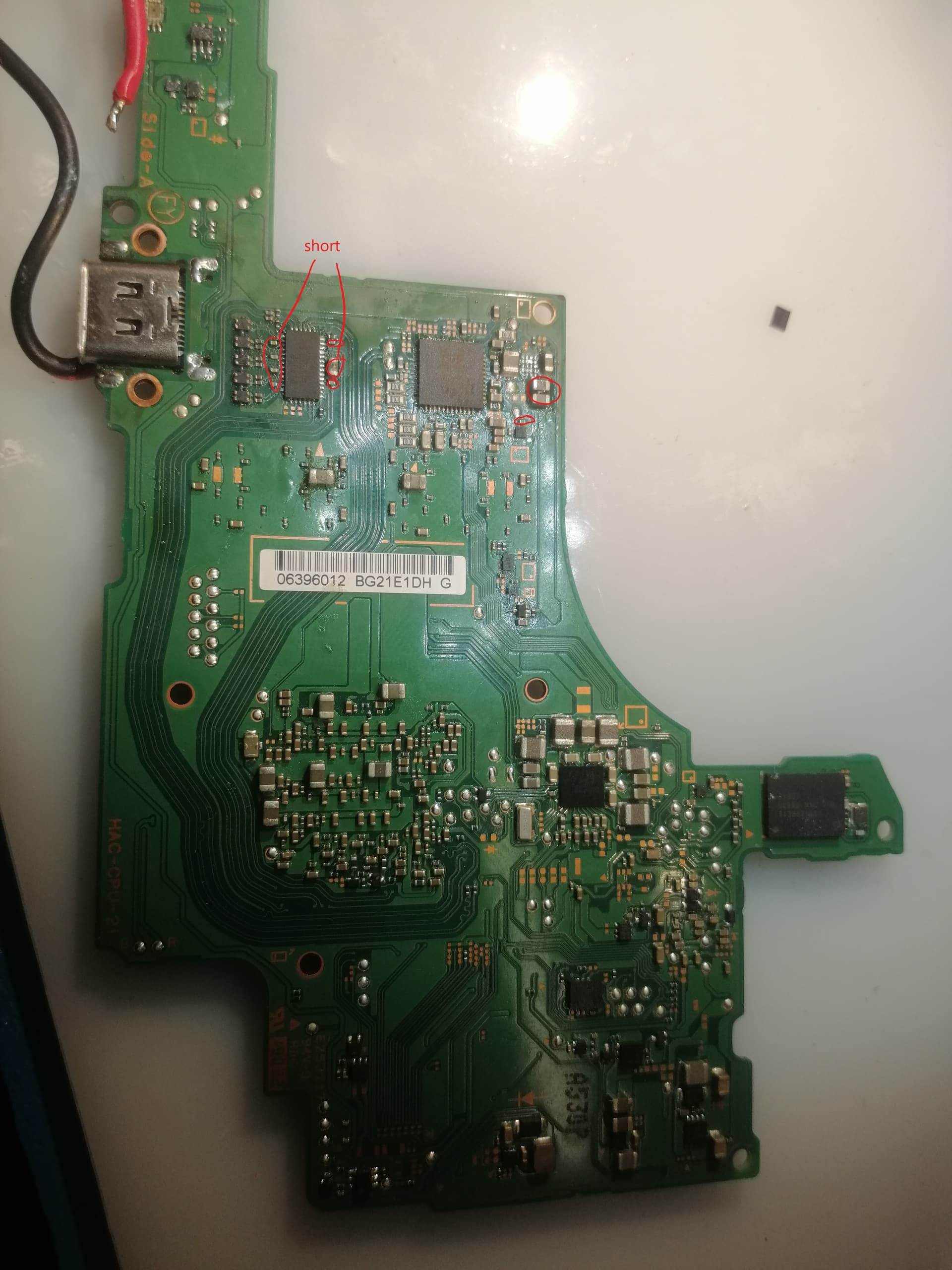
i found some more shorts
Because on the contrary to what the youtubers might say, “injecting” voltage should be an absolute last resort. besides that, you could have easily found the short the OP had by simply switching your meter over to resistance and measuring a few areas where this rail shows up relative to ground and you would have found this short in a few seconds far before you’d even soldered up your PSU wires, set up the thermal cam/used IPA etc ![]()
Maybe I’ll make a dedicated post on the dangers of doing this one day as there are cases where this can and has got people into hotwater - incl destroying the SoC on Switch being the most memorable and relevant to this scenario in my mind but it’s a complex topic, so ![]()
Had a feeling ![]() nice work
nice work ![]()
honestly my DMM sucks. I don’t see any different resistance on short to ground line from different area if they’re on same rail.
hmm ![]() you should be able to see the difference even with just two digits after the decimal place. If no, maybe you should pick up the UT61E which is dirt cheap and a good all rounder.
you should be able to see the difference even with just two digits after the decimal place. If no, maybe you should pick up the UT61E which is dirt cheap and a good all rounder.
You can see in the OP image the I/O (if i remember right) on the P13 is shorted, so this is a good example of how things could turn south, for instance 3V3 is bridged over to them I/O / GND - voltage is being pulled low, or short circuit, OVP or OCP has kicked in and hopefully kept the system safe but now somebody comes along and connects there bench PSU bypassing all the protection mechanisms and you’ve now got a dead SoC because of 3.3V getting where it ought not too, now I don’t recall if the I/O in question is sub 3.3V or not but it’s just an example… I’m sure we’ve all seen those switch boards where the first few pads at P13 are charr and the SoC has died (and a few where it’s miraculously survived) though I’d guess these cases are USB high voltage getting where they shouldn’t
this is just one example mind, the other common one on switch is SYS bridge to 3V3PDR or 3V3PDR bridged to 1V8PDR or any combination of the above for any variety of reasons and “injecting” voltage would kill the SoC again in pretty short order
LOL, I’ve been using UT61E for 2 years with 8mOhm gold plated fine tip prob. I don’t recall much different on resistance. Maybe I am more used to diode reading.
Haha then yes you should have no issues seeing a difference on the tail end of the decimal place as the miliohm range is very good on this meter. Just ensure you ground point is consitent and stable (I’d solder a line to the board and croc clip to the meter for this) - If your still having issues (though I’m not sure why you would) you can put a known value resistor in series with one of your probes (this helps with shitty fluke meters…which is pretty much all of them) - the general reading itself is not the part of interest, just the difference on said shorted rail around the board - I’ve been able to pin failures like this down using this meter to single caps in a few seconds on a good day ![]() though sometimes you do get small areas where a rail might be on 20+ compenents in a 1CM area and it maybe too close to deliniate on the meter but after narrowing it down to this area you should be able to spot the failure in these cases visually or just start pulling things off or IPA etc
though sometimes you do get small areas where a rail might be on 20+ compenents in a 1CM area and it maybe too close to deliniate on the meter but after narrowing it down to this area you should be able to spot the failure in these cases visually or just start pulling things off or IPA etc ![]()
Well, TBH, I don’t really know what I’m doing. I just watched some YouTube videos about fixing electronics and stuff, got the tools I thought were necessary, and tried figuring it out on the go. I have no background in electronics and just started fixing stuff about 2 weeks ago. I guess I have a lot more figuring out to do regarding not killing my switch while trying to fix it.