Hi, I bought 2 Nintendo switch that weren’t turning on. The first one had already been opened and I think they tried to reflow the cpu (I will keep this one for pieces).
It is with the second one that I am having a hard time finding where the issue is coming from. When I first opened it there were some signs of liquid damage around the BQ chip and on the other side of the board, under the charge connector. I cleaned that up and then went to check for shorts around the BQ, M92 and PI3USB chips and found none.
I reassembled everything and no backlight, no screen, no sound coming from the console. Fuse is ok, 5V 0.4A constant, charged the battery externally and still nothing.
I tried to put the switch in rcm mode, it is recognised by tegrarcm and I can inject payloads but the screen doesn’t light up.
I also tried the screen from the first switch but didn’t change anything.
I don’t know what to do, so I was wandering if anyone had the same problem or maybe knows where to look ?
Thanks
So under the battery connector was most of the liquid damage and I saw that the fuel gauge was damaged. I replaced it with the one from the other switch and it didn’t change a thing.
Have you double checked continuity from the battery connector through to the test points? Water damage around there is notorious for eating the weak solder joints on battery connector.
Could the screen be functioning, just not with a backlight? Under the right light in a dark room, you can see if the LCD is running. Other obvious thing to check is damage to the LCD connector…
Hi sheriff, thank you for responding. Yes there is continuity between the test pads and the battery connector and the battery is charging at 0.4A. I didn’t see anything on the screen but I will try to look at this today.
So I have checked the continuity from battery connector to test points and they are all good.
I have looked at the screen in the dark with a light but didn’t see anything. The screen connector looks ok and I tested with the screen of the other switch I have and nothing.
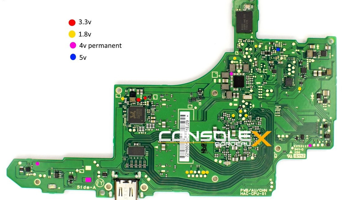
I have measured VBUS = 5V, VBAT= 3.9V and VSYS= 3.9V around the BQ chip. Is this ok ?
Also whether everything is connected or just battery and charger on the motherboard I am getting 5V 0.4A shouldn’t it go to fast charging ? what are the components I should look at ?
So 0.4A is basic trickle slow-charge which is what happens if either the M92 cannot discern what type of charger is being used, or the SOC hasn’t given the BQ permission to fast charge. The latter is probably what you’re experiencing here as fast-charging does not get enabled until later in the boot process.
A 0.4A pull is typical of an issue with an early boot failure, or a failure to mount the NAND or a power subsystem issue which is preventing the power-good signal to the boot processor.
When you say you can inject payloads OK, do you get the 0X7000 success message in TegraRCMGUI?
If so, then that’s not a good sign as a payload like LockPick or Hekate (text mode version) run exclusively on the Boot processor and don’t need very much to get up and running.
You mention that you don’t get 5v. I would probably ignore that at this point as that power rail may not get powered until later in the boot process as it drives joycon charging and system fan (i.e. not immediately essential for boot)
1.8v showing 0.5v is a problem however as it’s pretty fundamental to everything on your board. Normally the PI3, BQ and M92 screw with the 3v3 rail when they go wrong, so I’ve not seen a compromised 1v8 rail in a while.
Two things to try:
With the board unpowered, pop off the NAND daughterboard and re-run your 1.8v test.
Have a closer look around your BQ chip. There is a 1.8v logic feed supporting the BQ and the fuel gauge IC directly under the battery connector. If you’ve had water damage, then you may have a failed cap that’s shorting or a knackered fuel IC (inspect it for cracks or damage)
I thought I did have 0x7000 in tegraRCM but doing it again I always have « smashed the stack successfully with a 0x0000 ». Is it because the switch is patched ? (I don’t have the serial number)
Right, for the moment I forget about the 5V. For the 1.8V with or without the NAND chip it is the same : all the test pads are good except for one that is 0.5V (the soc is on the other side…)
Ok, so you think that M92, BQ and PI3 are good ? Or at least aren’t causing the 1.8V fault ?
It is the same if the NAND is plugged in or not.
Found the 1.8v rail close the the fuel IC. Trying to clean up the water damage, a capacitor broke off and saw that the fuel IC was damaged so I took the two components from another board but I didn’t reballed the IC so I am unsure if it worked. What is the purpose of the fuel IC ? And could this be the fault ? I will try to look at this tomorrow.
found the surface of 17050 is crashed, then changed a new max17050 but same. Unluckly I had crashed the cap just at the bottom of 17050 during install, so i replaced the new cap 10nf. I am not sure the cap is placed correct or not. I just know that is different color with the other 3 caps around 17050.
caps around bq, m92, +17050 are normal
battery installed with usbc pc charing 0.4a
rcm mode payload (Lockpick_RCM) can inject Smashed the stack with a 0x0000 byte, seems cpu is patched. I also dont have the serial no. of this board
1.8v test point near the top right of cpu side is 0.6v. Other 1.8v testing points are well during pc usbc plugged
So 0x0000 is a sign that the unit is patched and won’t accept a payload. Unless you fit a 3rd party glitching setup that you actually fit to the CPU, you’re not going to get around that.
The Fuel IC is pretty critical and provides battery consumption rate, battery level information. It is checked very early in the boot process and if the boot processor is unhappy, then it will halt execution before screen is enabled or logos are displayed (and also prior to fast-charging commencing - current >1A), so it’s an area to focus on. If you are unsure about your fit, then I’d focus on getting comfortable that it’s correctly installed (check to see if it isn’t lob-sided and there aren’t any bridged balls etc.)
Post a picture if you can to help us see what you are looking at.
The advantage of using an RCM payload is Hekate for example will still boot to the text mode UI regardless of the fuel cell status, so you can at least get a sense of the issues.
That was what I was thinking and I have no sx chip.
All right, so I have desoldered the fuel IC, cleaned it and the motherboard, reapplied solder on the pads and soldered the chip back on the motherboard. And it worked ! I am now trying to see what works and what don’t on the console.
So the console is now booting and it is charging but doesn’t seems to go to fast charging and it could still be the fuel IC if I understand correctly ?
Oh I didn’t know that about Hekate ! Shame it is patched then.
Edit : was using the wrong charger I am now getting fast charging… Thank you very much Sheriff for the explanations and you have been of great help here and on the other topics and forums. Take care.
Wonderful news! That must have been a great feeling when it booted.
So I would say your fuel cell is fine and not causing the charging issue. There can be several reasons that are worth exploring.
Does it fast-charge with the Nintendo charger? A standard phone charger works differently in terms of interfacing, so a good test.
Check the USB-C for damage or being firmly connected to the board (doesn’t rock from side to side)
There is an ESD device that sits on the CC lines that can go, meaning that the M92 cannot negotiate a faster charge rate. It’s optional in some territories, so you can remove it without issue. It’s on the underside of the board near the USB-C socket.
Does it dock?
Potential damage to the M92, but don’t go to the trouble of replacing this until you’ve exhausted all other options.