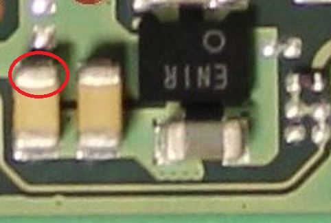
Can you plug in battery and prompt the console to boot and measure the voltage at these two locations and let me know the readings?
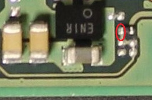
Can you plug in battery and prompt the console to boot and measure the voltage at these two locations and let me know the readings?