Hi guys,i’ve soldered everything back,and now switch draws 0 amps,dammit.Now with a good battery and charger connected,i read about 1volts on pin1 of BQ,0 volts on pin 6 of M92 and 0 volts on P13usb capacitor.Hmmm which other voltage/test/measures can i do on board?
So it’s possible you have a short to ground on your SYS rail (can be found on the large 2R2 inductor near BQ IC) or the USB fuse is open.
you used stencil and solder paste for the max IC right? as I’m getting the feeling this has not been soldered properly? (SYS is Vin for all the Max ICs)
You have to be really careful with all these Max ICs as a simple solder mistake on any of them can permanently kill the SoC which is why I mentioned measuring resistance to ground on the surrounding components following reball to ensure all is well.
refrain from powering the board for now ![]()
Hi Severence, I put the new IC’s from Blister, the solder balls look ok under the microscope, tonight I will check the ground resistance values around the components I replaced. Where can I find schematics with good values to compare them? Are there critical testpads to understand something? Thanks for your help
I see, I didn’t realise you could buy these Max ICs preballed.
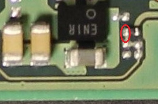
Did you wick the pads on the board too?
Can you let me know the restiance to ground at pin 1 of the BQ IC and also your SYS rail?
Sorry there is no schematic or board views which I’m aware of, I typically just compare to a known good board if I dno’t kniow the nomal reading off the top of my head, but feel free to ask and I’l let you know if a reading is good/bad.
There are a few but the ones that matter in most instances are connected to the primary/critical power rails, of which some may not have a dedicated testpads, just depends really.
power rails (if switching) will typically have an inductor, and inductors will typically (but not always) be inline with the rail output, generally speaking if you see one, chances are you’ve identified a power rail of some description
Anyway, I’m off on a tangent ![]()
The IC you removed is responsible for generating the voltage for the GPU, it just so happens though that it’s provided it VIN from SYS (which is regulated battery voltage) but the GPU buck also has ties to 1V8PDR which likely relates to enable lines (though tbh hard to say without the datasheet)
yap cristal clear
PI1 BQ IC=Mohm decreasing
Is SYS rail 2R2 to ground?If yes so it’s Mohm decreasing slowly
Resistance to ground of the inductors near the 2 max77621 left Soc are 50ohms,under Soc 260 ohms.
Fuse near usb-c is good and i have 5volts
What is the battery voltage?
That’s the one, do you get a voltage here?
I’m thinking it’s either the battery just needs a while to pick up or the BQ IC has died possibly or maybe a component surrounding it.
Is the console patched?
![]()
yes i got 3,961V with battery connected( im using a new known good battery not the stock one)
i’m not 100% sure but i don’t think so,for what the boy says,i don’t think he know modding,he buyed switch used from a guy and it worked for more than 1 year
Might be worth booting Hekate and checking the console info page to easily verify M92, BQ and fuel guage etc if you have a jig ![]()
Interesting, I’ll have to have a think on this.
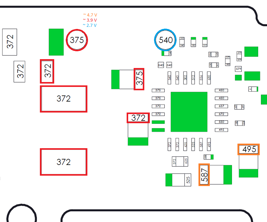
I found this voltage diagram made by Calvin,so i did some tests
with battery and usb 5v chargher connected,i found good values only in the red points(3,9V)
Orange points gives me about 3,76V on left cap and 0V on the right cap.
Blu point reads 0V.
i’m also interested in voltage readings about dual mosfets and transistor near fuse and also near M92,cause i don’t think voltages are correct either.
Orange right cap reads 1,1V(charger was not on,the other values are the same as before)
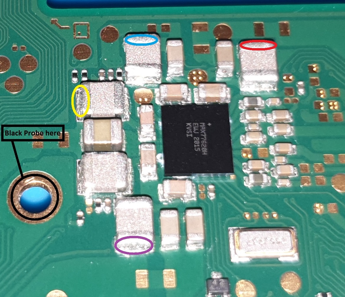
And i also found this Severence from one of your reply posts and i measured rails resistance to ground.
RED 4,3k
BLUE 30M
YELLOW 42ohm
PURPLE 1,1Kohm
So the SYS rail provides VIN for for the EN IC (as far as I remember), which regulates 3V3PDR (the “ENXX” IC can be found below the realtek IC)
3V3PDR is connected to pin 6 of the M92 IC, if you measure 0V here after promting the console to boot, then something must be dragging down the 3V3PDR, I would measure the resistance to ground here.
Either that or the EN IC has failed or it’s not being told to turn on as a result of another fault.
So afaict the fault is most likely going to be an issue with the M92 or the soldering, the USB port or the BQ IC and maybe even the fuel gauge.
If the measurments above are good then I would start by removing the M92 IC and seeing if the console will boot battery only and if by removing the M92 IC 3V3PDR returns.
Alternatively, Hekate makes this process quite a bit simple and strips out a lot of this manual work.
That’s fine
I’m going to disregard this measurment as low end meters have trouble taking accurate in circuit readings here (even some flukes)
This is interesting,i’m getting 5V on pin5 and 0V on pin6 of M92,with battery and 5v usb charger connected.
Usb detector shows 5v and 0 steady amps,so i think it’s not booting at all right?Soc is cold too
Aww ok thanks did not know about that,btw im using a Brymen 235 from EEVBLOG,not the top like FLUKE but i think it’s a good one
Pin 5 is unrelated to pin 6 (3V3PDR). So with 0V on pin 6 (3V3PDR) but with the SYS rail present you should ordinarily see 3.3V here.
CPU(0) (or boot CPU if you prefer) is active, which afaik would/should enable the EN IC.
So you should measure the resistance to ground on pin 6 of the M92 IC and we’ll see if something is dragging this rail down which might explain the problem.
Though it could be any of the other faults I mentioned previous.
It’s a quality meter, but just as prone to false readings on this rail, it just so happens that low end meters meters measure this particular rail (1V8PDR) incorrectly more often. Don’t worry about it, the rail is fine and fits what I expect with your meter type ![]()
I read Mohms on pin 6
with only the charger connected i get 0,6V on pin 6,but when i connect battery i get 0,dunno if it is interesting.
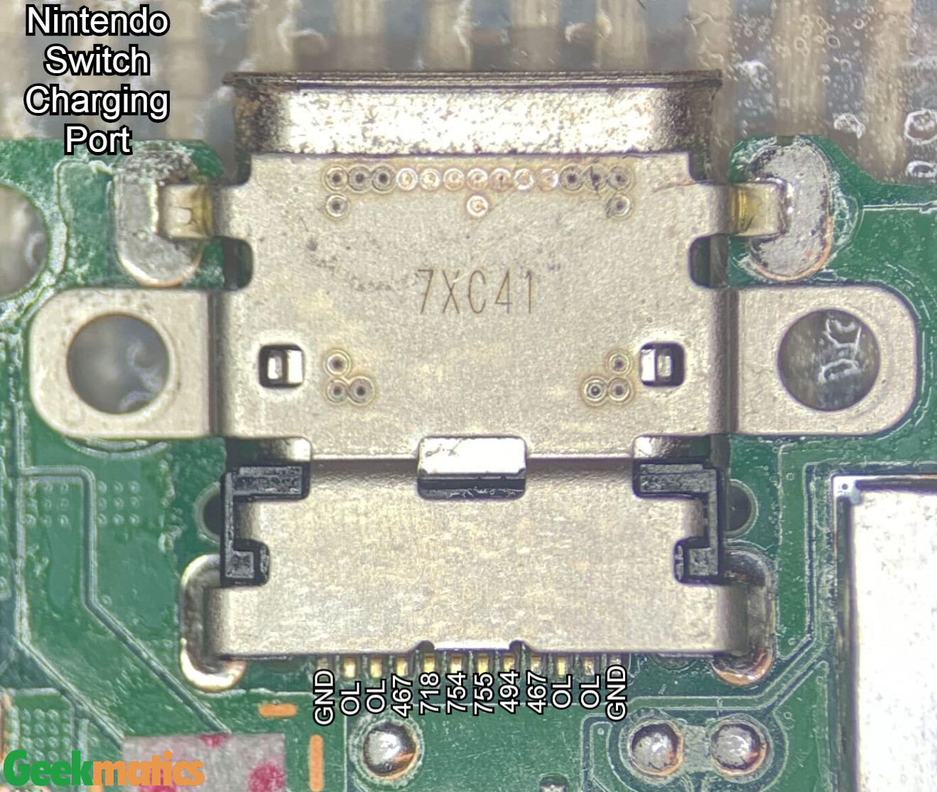
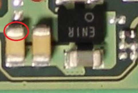
I also measured usb-c connector pads in diode mode,and values are good except the 2 pins in the middle,that reads strange higher values,not 0.775V but about 2,5-2,7V,is that normal?
It’s rather high,
Is that with red probe on ground?
it’s possibly indicating a USB fault or an SoC fault, whats your resistance to ground here?
Can you plug in battery and prompt the console to boot and measure the voltage at these two locations and let me know the readings?
Yes
(754) gives me 2,45V and resistance to GND is 35Kohm
(755) gives 2,9V and resistance to GND is 90Kohm
Just a heads up calvins charts are diode mode measurments, no battery/power should be applied, just in case that’s whats going on here.
In terms of resistance (again no power/battery applied) your readings are too low, you should be reading high megs, typically around the 5M mark though it depends on the board revision.
Though, this is the problem with taking random measurments here and there, they don’t really say much as everything is interconnected and a fault elsewhere will have a knock on impact somewhere else (if that makes sense)
What’s your voltage readings on the points I highlighted above, maybe that can shed some light on whats happening
yes i did all measurements with battery and charger disconnected
Do I have to reconnect all the cables and press the start button on the side of the body? I’m not sure I understand, can you explain the correct procedure for the test? Really thank you very much for the time you are dedicating to me
So by “prompt” I just mean pressing the power button, or using the USB to tell the console to turn on. If your pretty confident the USB is fine then it’s simpler to just use that to do it. The board and battery alone are enough for these tests nothing else needs to be connected (aside from the USB initially)
Alternatively you can connect the power button, vol +/- flex and use that instead of the USB.
Or you can bridge the corresponding pins of the flex connetor directly.
Or there is a testpad somewhere, though i forget where off the top of my head.
No worries, just making sure ![]()