that’s cool i will check on this
But prior i think i have spotted a cold joint on solder ball under max77261,the one that i have changed
time todo a reflow with amtech flux to be sure
that’s cool i will check on this
But prior i think i have spotted a cold joint on solder ball under max77261,the one that i have changed
time todo a reflow with amtech flux to be sure
Good spot ![]() those ICs are a real pain to peak under because of the surroundings
those ICs are a real pain to peak under because of the surroundings ![]()
Though this is almost certainly not going to affect your previous measurments so don’t think that’s the primary issue here (because the ball/pad is open if anything and not shorted to anything else)
After reflow,nothing changed so far,solder seems good now
switchbrew orgTestpads
i found this link,so power button tespads are in Cluster E11 and J4.
What should i do after battery connection?
So see how it says “active low” it means pull low to activate essentially.
You’d just bridge either of those points (take your pick) to ground to “press the power button” which is effectively what your doing when pressing the power button, pair of tweezers will work.
Will say though, I’ve not verified a lot of the TP listed on this site, so do it at your own risk, or buzz these points to the power/vol flex connector and see if they are the same as the pin here to verify if your not sure ![]()
I think i’ve made it right,i have 3,3V on big cap and 1,8V on the small one,are those those M92 pin18 VDDIO and 3v3 pin 6 rails?
Well done ![]()
So pin 18 of the M92, is connected to 1V8PDR,
Pin 6 of the M92 is connected to 3V3PDR (the big cap I highlighted near EN IC)
The left side of the resistor I asked you to measure is a 1.8V enable signal (which is in sourcing it’s voltage by way of 1V8PDR but is not a direct connection to it) from the SoC to tell the EN IC to enable the 3V3PDR output.
So if i understood,the Soc is alive right?![]()
But now what can i do?Test again M92 voltages with this method?
It’s got a heartbeat ![]() it’s at least partially ok, but no guarantees just yet
it’s at least partially ok, but no guarantees just yet
Right, you should see after prompting the console to boot 3V3PDR at pin 6 now, which means your EMMC and other ICs on this rail will now have power unlike before.
You might wanna try now with the bl/screen connected
Why your USB is/was not prompting the console to boot earlier though is another issue.
If it’s not a USB connector issue then think it’s going to come back to one of the three ICs i mentioned earlier. I hope you’ve got a jig on order ![]() it’s so much easier
it’s so much easier ![]()
YES i have both 3v3 and 1v8 up and running!!!
i have to tell you,now i’m excited
tried with everything hooked up and nothing coming on the screen,awsome
i have 3v3 and 1v8 on M92
still 0 amps from usb connector
RCM jig is coming tomorrow,
even if I don’t know how to use it yet, but if I understand it should allow me to understand what state the console is in via the usb cable connected to the pc, and do some checks, I’ll give it a chance at this point.
If there was a sure way to know the Soc is fried, I wouldn’t really be wasting my/your time, even though I’m learning a lot from this experience.
The USB is just for the initial payload upload after that it’s not needed, the Hekate payload will provide some insight into a few components on the board.
Hopefully you still have USB comms though based on your previous tests. It might be it doesn’t.
you’ve been performing all the preliminary tests to validate the SoC without even realising it ![]()
Those USB pins you measured earlier can sometimes be an indication but sometimes a bit of a false trap, the rails produced by all the Max ICs etc which are all fine. there’s a few more points which you can test in circuit but tbh it’s very dependent on board rev and the results are not 100% conclusive, there is no guaranteed way to know for sure without removing the SoC and measuring the corresponding rails out of circuit.
lol sorry i’m really ashamed of myself ![]()
I have tried a few things in the meantime that the jig arrives. I have installed tegraRCMgui on the pc and the APX drivers.
I did 2 tests, one I connected the switch to the pc via usb cable without battery and without emmc and nothing happens, then I connected the good battery and the memory, and still nothing, I don’t know what to think, it should see it if it were in autoRCM quite right?
How should I do with the jig?
You may have to prompt the console to boot manually as we know the USB isn’t going to do it. with battery connected and EMMC disconnected.
It may be the USB is faulty (and the dodgy readings your got earlier) on D+/D- will prevent USB comms, or this could be caused by the SoC or something elsewhere.
If that’s the case though I’d expect “USB not recognized” message on the PC.
ok did that but nothing happens
What’s your resistance across both pins/pads? black probe on one and red probe on the other
And also what’s your resistance to ground on these pins/pads with red on ground?
108Kohm
form left to right 89Kohm and 17Kohm(red probe on gnd)
91Kohm and 35Kohm(black probe on GND)
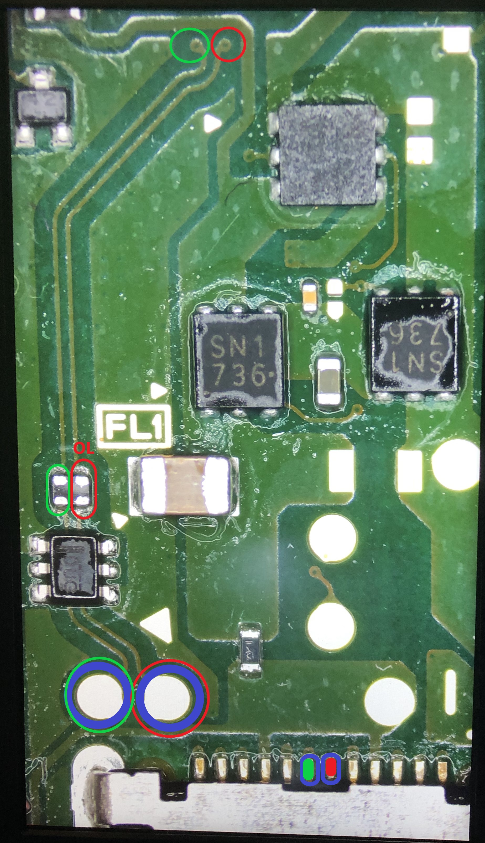
I found something interesting following the signal path,
an EMI filter i think is blown,because on one side it gives me OL,what do you think?
I see, This is quite low, again, would normally be high megs.
But the issue is your diode mode readings from earlier and resistance readings aren’t agreeing with each other which is making me suspect a meter issue here in this case which maybe skewing readings somewhat.
Yeah that’s definately an issue,
I would replace the filter and just as a matter of course take those resistance measurments again as it will surely change them, don’t plug it in just yet, though if they remain in the high Ks both polarities, no real damage should occur with USB connected
It’s also entirely possible the diode has failed also
i don’t have a donor boards atm so i cannot replace now the filter.
Can i short circuit at least the blown side just to see what happens or is it dangerous for the circuit?
So I would jump the filter on the side which is open,
Take those readings again with your meter no power, if the readings remain strange, remove the diode just below it and repeat taking the measurments with your meter again,
If everything measures fine (high megs) in all polarities then it should be fine for testing purposes
I’d also check the diode on the other side of the board
You could also rule out USB removing the filter and taking diode/resistance readings at the two points again should be OL