correction: *filter and diode
Ok i did the jumper on filter,now the resistance to ground between the two pads has raised to 8 Mohm
Resistance to ground has raised to 9-10Mohm just from the jumped pad,the other is equal to earlier measure,and it’s 90Kohm
PS same for diode mode,the jumped pad is now good 725,the other is still high
Hmm can you remove the diode just below and see if that 90K reading jumps up… though it would be a strange failure mode if it has.
Ok here is the situation,emi filter removed and jumpered both sides,6 pin diode under emi removed.
Resistance to ground and diode mode from right pad is the same as before.
Now left pad measure 50Mohm and OL in diode mode
So correct me if I’m wrong, you now have approx 50M on the left and 10M on the right relative to ground?
If yes, that’s good, I’d check that same diode on the reverse side of the board also ![]()
Correct,but with 6 pin diode connected,i read 2,88V in diode mode on left pad,and 775 on right pad that seems good judging the values of a good board,it should be same value or am i wrong?
How can i test the 6 pin diode and diode on the other side?
That would be indicating a fault with the diode, so leave that off the board.
If thats what you read on a good board, then I think your meter is playing silly buggers with you ![]()
Same way
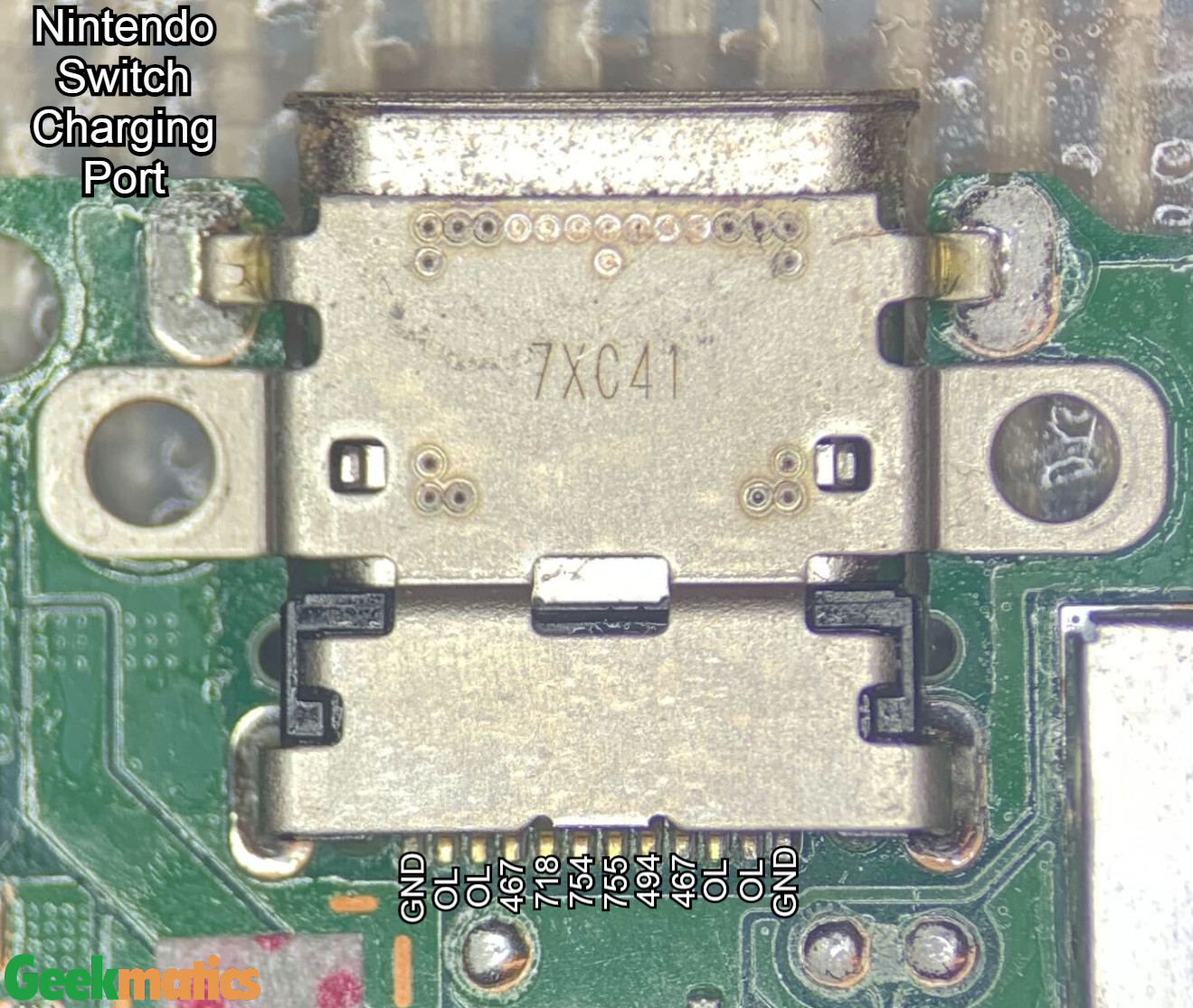
I was referring to the diagram found on the net, the value of the left pad watching the image,now correspond
I meant how to measure it with the multimeter, if I unplug all 2, to see if they are faulty, I have never seen a 6 pin diode LOL
to test the diode on the other side i have to disassembly motherboard again so i would check first this diode,i’m about to give up,this is turning in a mission impossible mate
Right, so ordinarily you should be reading approx 0.8 on both pads in diode mode (with or without diode present)
but because your meter has been giving odd readings it’s hard to say. So it’s possible the line is open, or it’s your meter one of the two.
dual package diode as far as I remember, so from memory it would be center pin to the common ground pins… though I could be wrong. then flip you probes.
Provided the line isn’t truly open on one of those two pads top side, then you can test with USB with the diode off the board, if the other diode is bad in someway then it means it simply won’t work with the USB in one orientation
Switch prompted to boot,3v3 and 1v8 on M92 are present,good battery connected,emmc not connected
still 0 amps on usb detector,and windows not detect switch
Think i’m done,man this Swtich has passed through the hands of too many people, not knowing what they have done, it really becomes a difficult undertaking.
I don’t want to waste you too much time and just give us a big headache, on the weekend I will return this body to its owner, it was still a great experience and I thank you for it, I wish you all the best for repairs
No worries man, this seems like it’s a bit of thrown in at the deep end and I think as you said, this has most definately had prior rework beyond just the Max ICs, hard to say what was done previously. Based on you prior results, it’s entirely possible somebody has attempted (and failed) an SoC reflow… but who knows.
All the best 