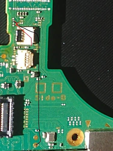
That via leads to a test point midboard front or back. You didn’t end up needing to find it but I promise you it exists somewhere. Could be on other side of board on Mariko. I was second guessing myself on seeing that via so its nice you confirmed.
Def a via on Mariko and a trace leading under connector on V1
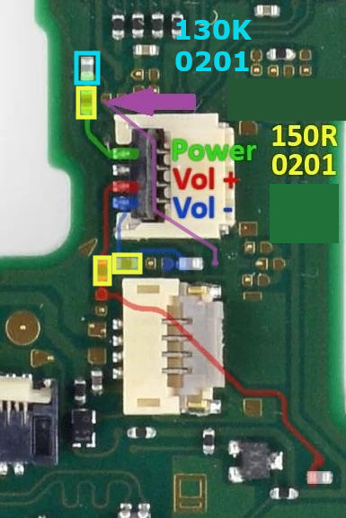
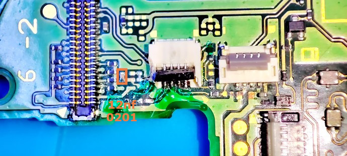
Hi FCE, thanks for the message, basically you are right, and thanks for editing the picture, i am not sure if the 12nF capacitor are for the one above or under the power ribbon connector, or even both, but at least what i am sure is that the 2 components coming in the line of the power button itself are resistors, that’s definitely certain.
For the rest, i confirm the trace under with my violet trace is working out, as you may have notice in my pictures, i even scratched it to validate it. At least it doesn’t force you to find another test point for some boards.
By the way, silly question, but haven’t found a post talking about it, what are the board revisions the Nintendo Switch does have ? I read a lot about mariko, V1, … but i don’t understand to what Switch revision we are referring to with those names. Thanks.
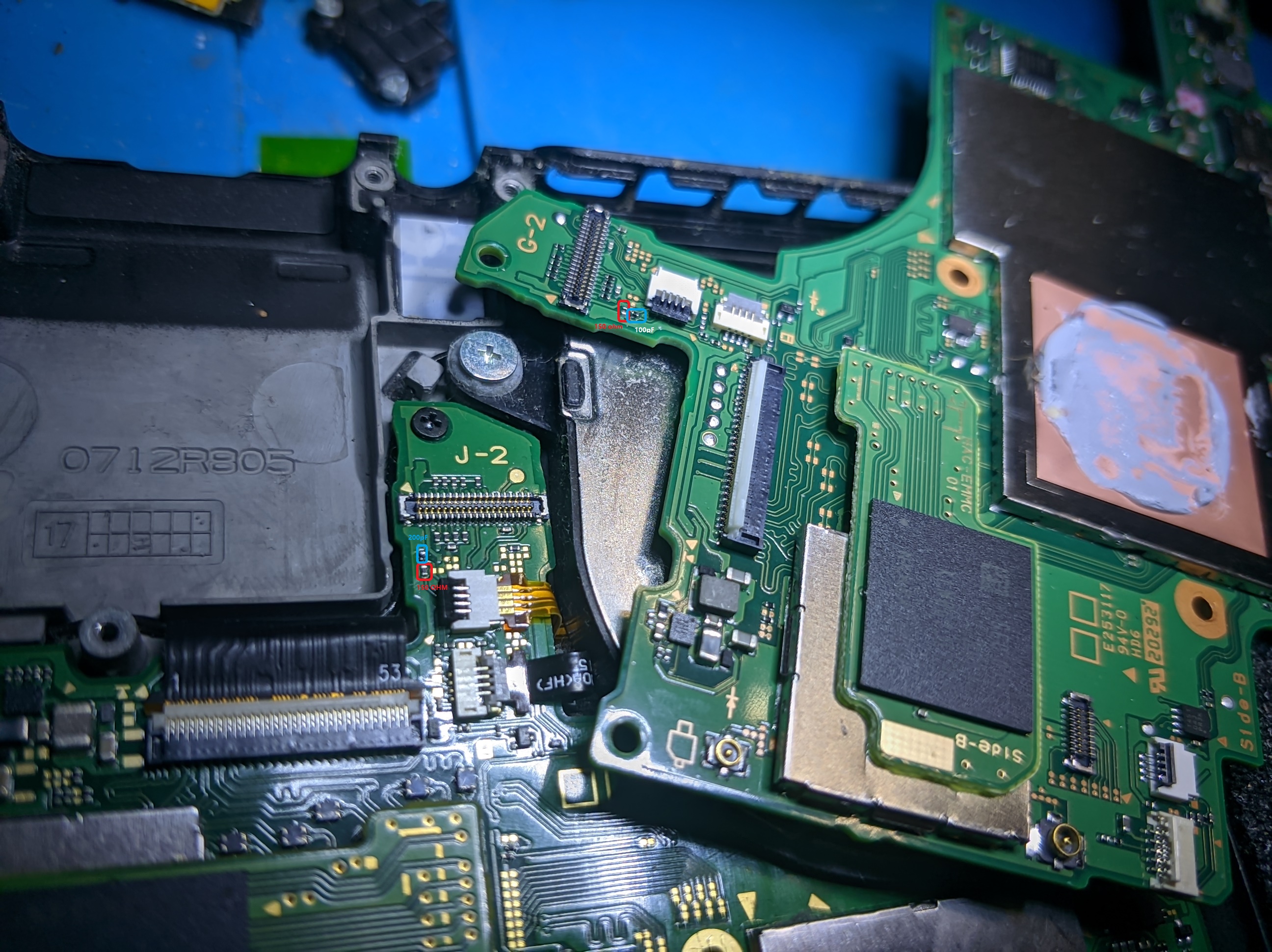
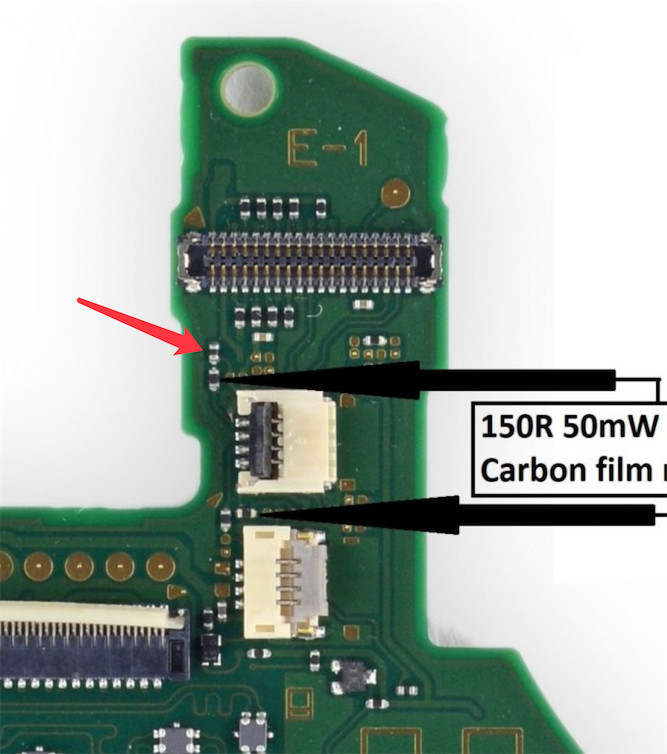
received 2 NS today. v1 and v2. From my measure( out of line) both “resistor” blue circled next to 150 ohm one from 2 boards are OL value in resistance mode and around 0.1~0.2 nF/100-200 pf from capacitance measure. This is what I bet your 130k measure is wired from me
ok got it, then i don’t understand why it is different in your case, all the boards i have at the moment looks like resistor, beside the fact that i get a funny value for the one that goes to ground. But for the example, the 150R on all boards i have (HAC-01, HAC-10 and HAC-20) are all measuring 150R, but in circuit in my case. And even the looking, both components are always black in the boards i have, while capacitors are brown, weird
"Can anyone help me with the one pointed by the red arrow?
“I pried the connector in the wrong way and this one is now missing. I tried measuring it on my good switch and it seemed to have no continuity at all, like an open line. However it doesn’t look like a capacitor either. I also have not been able to observe any ill effect after missing it.”
I only know of Mariko but have never put an iron to one. Basically all my experience is V1. Those two and OLED are the variations I’m aware of.
Mariko has better battery cause Tegra was reworked(smaller nm process or whatever). Almost all the parts are interchangeable between v1 and mariko cart reader,sd , LCD. Only Tegra differs.