I am trying to repair my first console, it’s a nintendo switch, it has a bad usb-c port, no short circuit on the others mains chips.
I managed to get the usb-c port out and overall I feel like I did a not so bad job. The board is pretty clean, I did’nt burned any chip, I only slightly burnt some plastic near the usb-c port.
But it needed some time and a bit more temperature (up to 480°C) and some resistances dropped off the motherboard (rookie mistake I guess)… I still have the resistances and the board seams fairly clean. Do you think it is possible to put them back on ? I feel like I can do this but I really don’t want to mess this up more than I did.
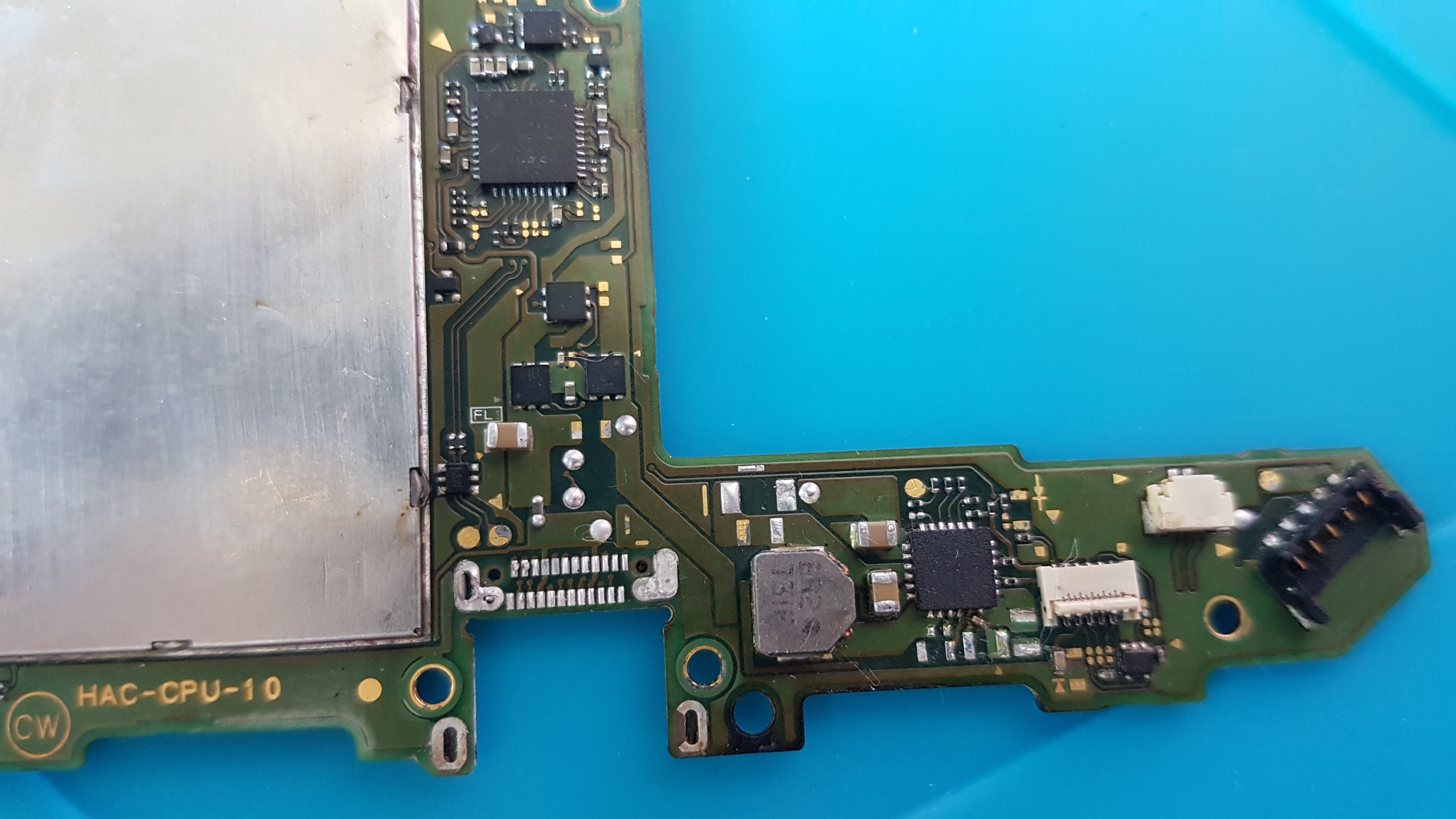
Here is a picture of the side of the board without the resistances :
Also, the usb-c port didn’t go out perfectly, it still has some connectors fixed to the motherboardboard. Do you have some ideas as how I can safely take them out ?
Picture here :
Did you use a big or small nozzle? (Small is better because you only heat up the usb port)
Its kinda bad when components unintentionally desolder but is fine for a complete beginner
The stuff that remains on the usb pads is leftover solder, just put some solder on a tip and go over all contacts then wipe with some solder wick over it to remove the leadfree solder and solder in the holes
Pieces of the old connector in the holes can be removed by pushing a tweezer into the hole while heating it with an solder iron
PS: The components are capacitors, resistors are the black ones ^^
I used a 8mm nozzle but I can try a 5mm one if that is too big.
Yeah it’s pretty bad, do you think it can be rebuild ? I think I can add a bit of heat until the solder melt and put them back on but I don’t think I have a lot of tries.
For the pads, can’t I just use the same solder to fix the next connector ?
If I apply some solder wick over all the contacts their will not be any solder left and I will have to resolder them. Is it not a bit too mutch work for a begginer ?
I think they may be 2 of the pads who have no more solder and 2 more who needs cleaning since they have too more solder on them. So I still have a bit of work on them to do.
Ok I’ll try that for the pieces of the old connector.
Yeah I wasn’t sure about the term I was using either, I was using google translate for that (french here !) maybe I shouldn’t.
Since you dont have missing pads its not that bad, you should remove the old solder so you can place the capacitors properly and solder them on
You should remove the old solder from the connector pads because it is uneven and it can be very likely that you have cold solderjoints because there is not enough solder
Removing the solder is really easy, use a soldering iron at 360-380°c with pencil tip, apply solder and go over the contacts, then put solder wick on the pads and gently wipe with the tip on the wick to remove the old solder
After that you can put down low temperature solder (on the contacts of pcb and connector, on the connector outside normal solder) so it solders easier with hot air; just put some on your tip, apply flux and go over the pads so that they are coated equally (You can also use normal solder but it is harder for a beginner to solder the hidden row of the connector)
You could check on youtube how to get rid of overdue solder, it’s not that hard but since you are a beginner you should take a look at some youtube videos.
If you need further support I can share contact details and guide you.
Thanks for your advices their are very helpfull !
I’ll look at some more youtube videos wile the missing parts and tools arrive. I’ll update when I have everything and think I’m good to go (or need further assistance).
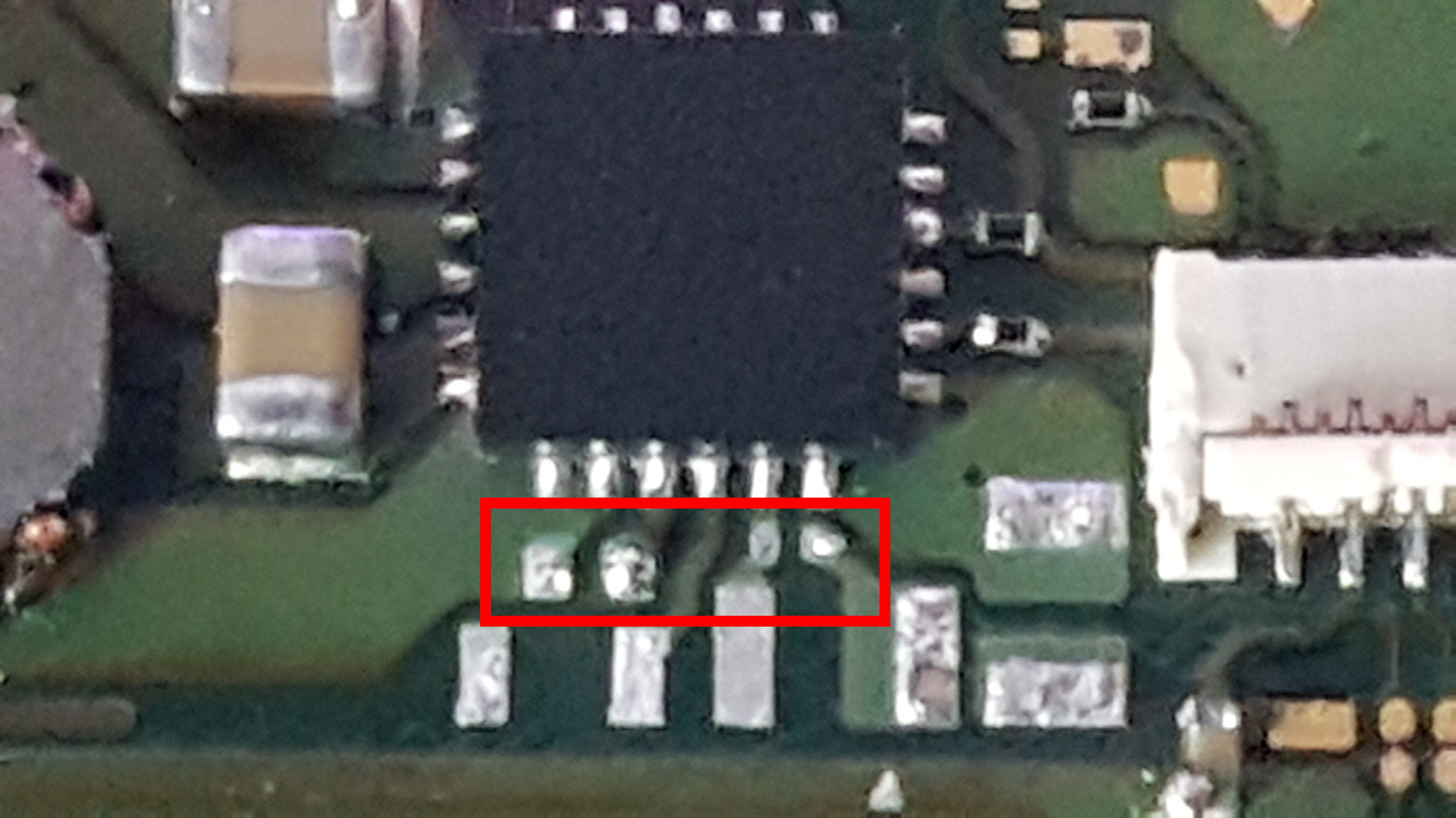
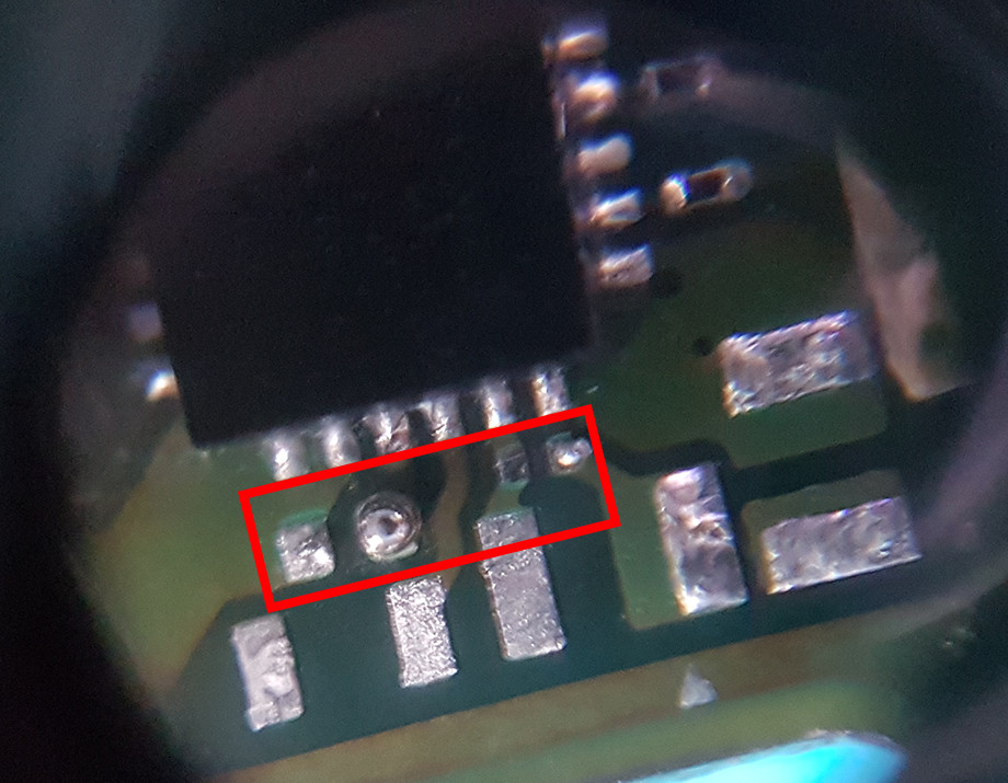
Some update, I am trying to remove the old solder from the capacitor’s pads. Right now, I am struggling to do it.
I have check some videos and I have put some new solder over the pads, then use solder wick to go over the pads up to 480°c, but it just won’t come out. I have added a bit of solder flux paste to help it flow, but the solder just stay on the pads.
Here is a picture if you need a bit more details :
Which soldering iron do you use?
480°c is enough to (re)move the pads from the board, 380° is usually enough
(with really high temperatures you “remove” the flux in the wick before it can work)
remove the solder from the bq chip & verify that there are no bridges before you solder on the capacitors
pads look clean enough, take capacitor which you want to solder on with tweezers, apply flux, place it onto pads and use pencil / “knife” soldering iron tip (with some solder on it) and solder on one side of the component; move it if necessary and solder on the other side
there are smd training kits which would be better than the (still working) mainboard, get one and try to place and remove the components so you have a “feeling” for it
Dallas :
No, at the time I thought low melt solder was for soldering stuff back and for not removing solder. So I ended up doing something useless.
I plan to reapply some solder (colder this time my solder wire is supposed to melt à 227°c so I am gonna try that).
BUT I have actually burnt my only iron tip and, since their is no shop selling the parts in my town, I have to order some new with a 2 weeks shipping delay. So there is that.
I keep your whatsapp/facebook idea in mind but I think I got this now.
DSch :
I use a Yihua 899D II station with a hot air gun and soldering iron, with a pencil tip given with it.
Yeah that what I figured out afterward it is useless to put too much temperature (I think ?).
I think there is no bridges, I have cleaned the board a bit (their where a lot of old flux on the chip) and it look clean.
That’s my next plan, but since I have burned my tip I have to wait again…
you should always use a low melt solder for removing chips and larger caps, and so on. my recommendation is that you are using 138-183C temp solder wire/paste (leaded if possible) for removal. the 183c solder could also be used for reballing and installing new SMD parts.
The reason why you should do this is to decrease the time with the hot air gun to lower the risk of thermal mass damages / small parts flying away.
If you don’t want to wait 2 weeks on the soldering tips there
is a technique that I could recommend:
Add some flux and then apply heat with the hot air gun until the solder around the chip until the solder becomes liquid, then you should gently touch the solder with a soldering wick.
I think I will wait for the tips to arrive since, as far as I understand what you are suggesting me, I will only take the solder off but I still have to put the capacitors back on with a solder iron.
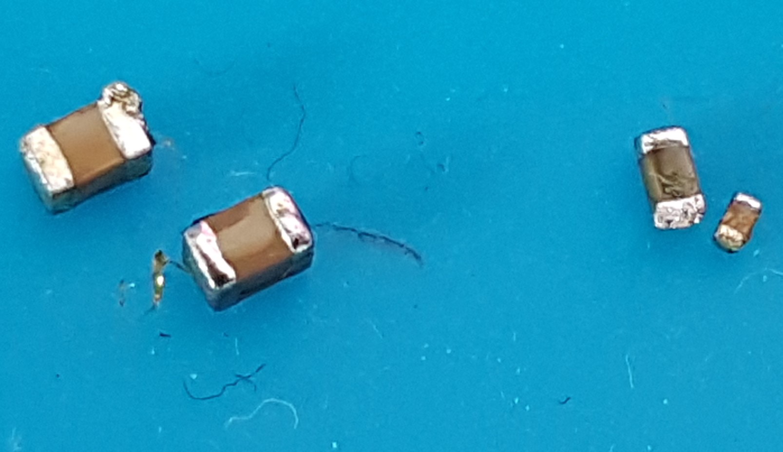
By the way, I may have broken the tiniest one of the capacitors (the one who is less than 1millimeter long). Is there any website who sells them ? If not I have a bluescreen donor, but it still adds to the pile of work.
I’m french, that’s where all the grammar errors are comming from if that’s the question
Sir, nothing is wrong with your spelling or grammar, just wanted to know where you are living because of the 2 weeks shipping time. Have you checked ebay EU?
And alls caps are for sale but we have no schematics and board diagrams to know the correct values, if you have a donor board you should take parts from it
Well I’m glad to here about it
Apparently the shipping times changed during that time and I may be able to try everything next week, so that’s not so bad.
Just, sorry but I didn’t get where the caps are for sales. Is it on the tronic fix store ?
I don’t know which caps you are looking for, but my point is you can buy all kinds of caps but first you need to know the values and size ”10uF 0402 Cerm Cap”
Hi everyone, first I’m terribly sorry for the long delay but I had an atrocious amount of work who just poped up at the time and I wanted to have all the time I needed to focus on this.
Long story short, I’ve managed to get some practice from soldering practice boards and after a week or two of try and error I’ve managed to understand enough for me to start soldering back those capacitors on my switch’s motherboard.
At first I decided that I would make a post when I would have finished everything, but it is not the case. I am AGAIN comming here for help …
So first thing first, I’ve managed to clean up the board a bit more, since there where still some old solder in place.
Some important details , I think :
When I was practicing soldering techniques I used my soldering iron with a smal tip, I managed to solder/desolder capacitors at a 250C° minimum (I could only find lead free solder wire and it was supposed to melt at 225C°, but apparently not. It annoyed me a bit but I guess that’s fine).
On the switch board however, it just would’nt melt at that temperature. Not with flux paste, not with some soldering wick, not with anything.
I’ve finaly managed to make it melt and clean it by increasing the temperature to 400C°, I was not happy to do this but it wouldn’t work otherwise. There’s still a bit of old solder stuck in the holes of the usb port that I can’t take out but I will try again later.
Right now my problems are :
_I can’t for the life of me make the new solder stick on the pads of the capacitors. It just stays on the tip of my soldering iron or it just sits on the pads but it won’t stick on it. I’ve cleaned it as best as I can and try new tips just in case the old one was bad but it still doesn’t work.
_Second, I have managed to take the capacitors I needed out from the donnor board to use them on the (I hope) still alive one. But, after a whole day of doing all of this my hand kind of started getting NOT that stable anymore and the smaller capacitors jumped out of the tweezer… Now there are somewhere on the floor and there are so small that I can’t find them anywhere… So I need help identifying them so I can buy a lot of them.
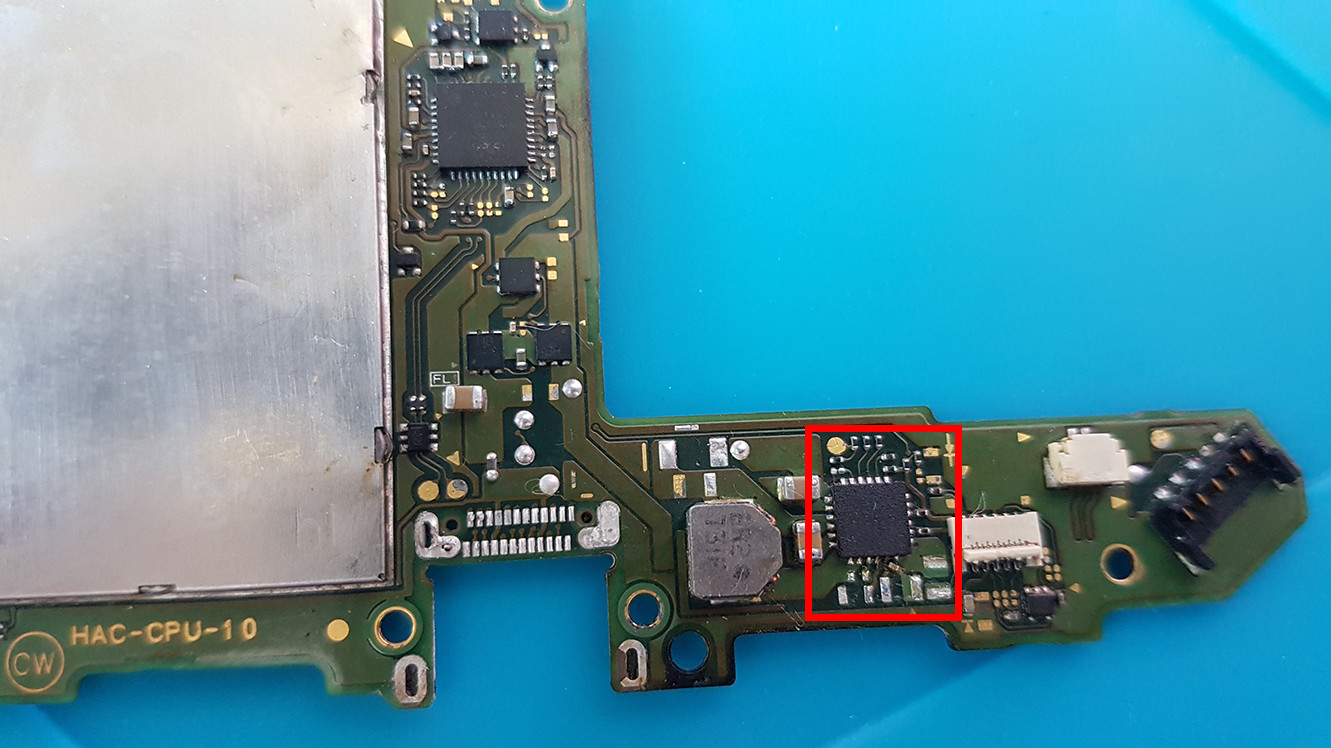
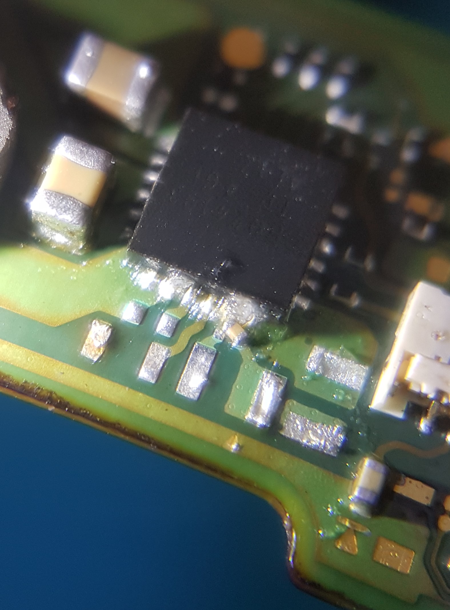
So we are looking at that chip and the capacitors at the bottom of it :
For the usb pad, you can use hot air 400C with flux melt the old solder and usb wick to clean up left junk and reapply new solder on each pad.(Highly recommend especially 2nd line/hidden line). I always apply solder on new port 2nd rail pins since you can’t tell if they sit well on the pads until cool down and test with type-c test board


 …
…