I have a customer who brought in their console which works perfectly fine handheld but not displaying to the tv on their dock. We tried their switch on another dock to make sure that wasnt the fault.
So orignal I thought this would be caused by te P13 chip so I went straight to there and tested the caps around it for any shorts but all seems to be running smoothly. No other shorts can be found on the board which is interesting,
Does anyone else know which chip or what else could be responsible for this error?
solitamente, il didetto che mesioni è causato dalla rottura della presa usb-c, con ic P13, si apre anche la prima impedenza, con bruciatura circuito.
Verifa e fai sapere.
Ciao
Make sure the board is getting 15v from the charger, if it’s only getting 5v, then you have an issue with M92T36.
The caps don’t need to be shorted for the chip to be defective, if the port looks good, check the 4 filters above PI3USB, if they all measure good, then go ahead and replace the PI3USB IC.
Test points to check voltage on side-B:
xhttps://www.tronicsfixforum.com/t/usb-c-charging-port-replacement/4316
For checking the filters, I take the board out of the Switch. First I would test (in diode mode with red probe on ground, black probe at the pins and unplugged battery/charger) the row of pins at the pi3usb ic towards the filters/usb port and make sure that all pads are imediately showing the right value if touched.
If all pads are ok, I would check the filters top to down for continuity and cross check that the two lines are not touching each other.
Thanks for all the info guys, I just want to preface that I am a really noobie getting into smd soldering and repair.
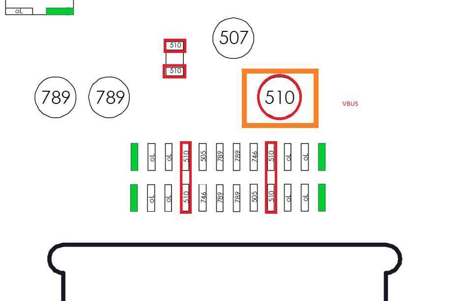
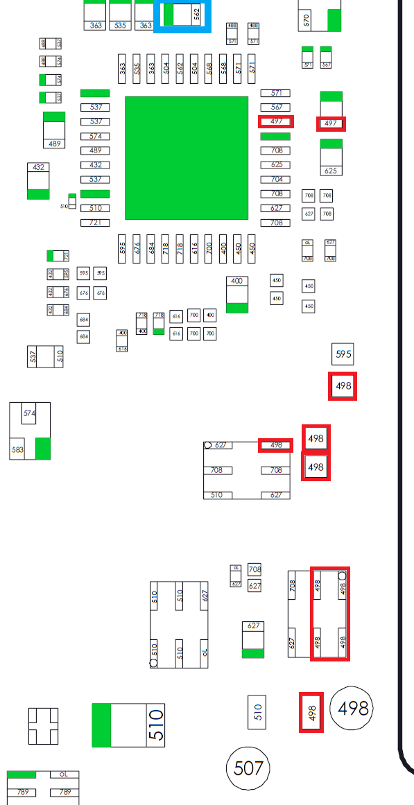
I have tried to test voltage by putting the red lead on the 510 (in the orange rectangle) and the black lead on the apu shield while having the charger plugged in. Then I think I shorted the m92 chip ( verified by the blue rectangle on the second picture and getting only 0.12A and error 2101-0001 while booting up )
On the USB C diode, I have all of the diode reading correctly except the 8 pin from the left (OL)
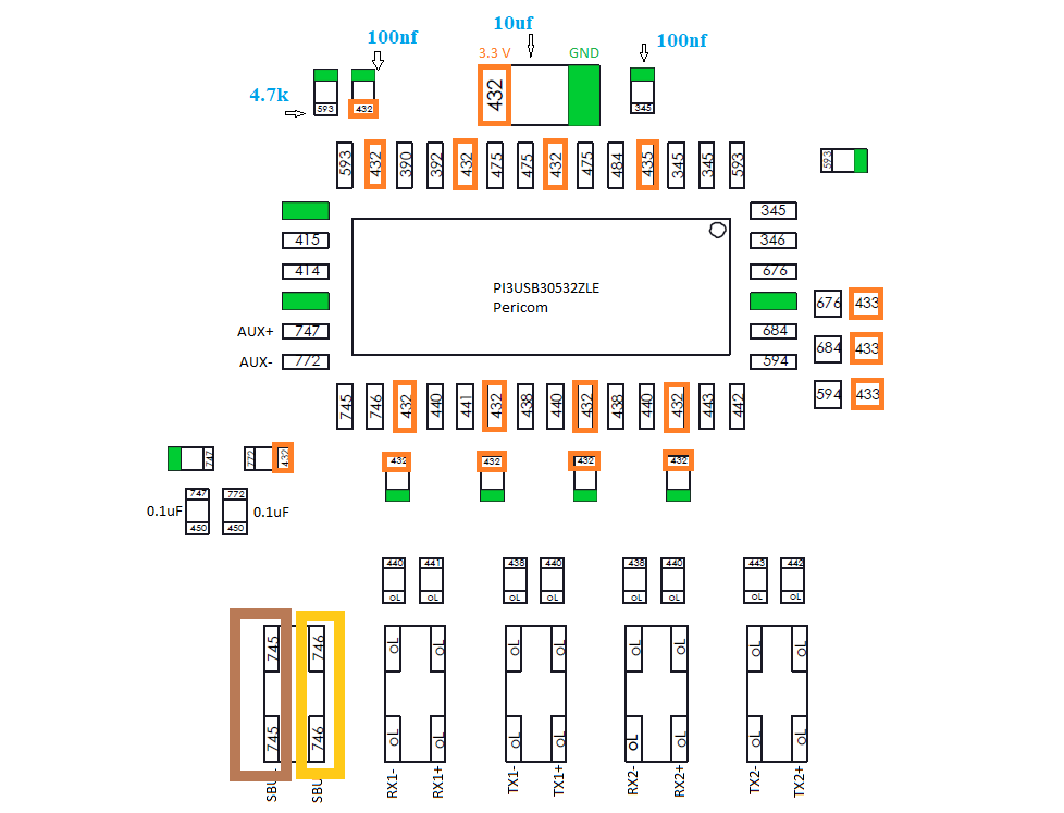
and last on the p13usb, I have check as much diode as i can with my thick lead. I am getting continuity in the brown box while not getting a diode reading (0L) while in the yellow box, I am getting a diode reading but no continuity.
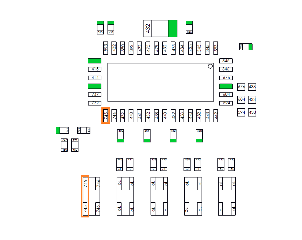
So at the first left filter you can measure aprox .746 mV on the pi3usb ic side and only OL on the usb port side. And you have OL on the same sbu line (8th pin from left) at the usb c port. That would indicate that the filter is bad. I would replace this filter.
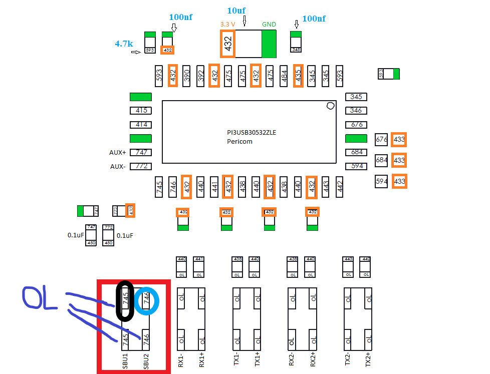
Out of the 4 locations on the filter, I am only getting one .746 mV ( I circled in blue ), I was expected to get .745 mV on the one I circled in black but the last 3 locations are OL. I will replace this filter first and get back to you thanks. I suspected that I screw up the p13usb installation since im missing .745 mV ( circled in black) would you be able to confirm that?
Sorry I think I got you wrong. If you have continuity through the filter, the filter is ok. If you can measure OL on the pi3usb ic side at this filter, it means that there is no connection to the ic itself.
I would check the orange marked pad at the pi3usb for burn marks and if it seems to be ok, I would test direct on the side of the ic (where additional contacts are) for the .745 V. And if they are present, I would resolder this pad or reflow the hole ic.
I think you will struggle with those tips because of the angle and surrounding components which will limit your heat transfer and because most of the pad area is not exposed
Might be worth opening a new topic for your rework station and I’ll help you diagnose and fix that… which maybe quicker and easier
Thanks man for the offer. The rework station is from aliexpress. After the handle shorted and fuse blow, the reflow station goes from 0 to 500+ degree C and it overheat itself (handle smokes). I only figure out after replacing the handle and the same thing happen ( 0 to 500 + degree). I don’t know if I can still fix the rework station. I bought one from Amazon to use for now. Im thinking if I should get the $200+ rework station and hope it don’t break down like these one.
Either this
US $195.00 | 110V 220V 900W PHONEFIX 861DW Digital Hot Air Rework Station Leed Free BGA Soldering Station Cellphone Welding Repair Tool
a.aliexpress.c.om/_mPSsS8h
Or
US $156.19 29%OFF | SUGON 8610DX 1000W Hot Air Rework Station LED Display Lead-Free Heat Gun Microcomputer Temperature Adjustable 5nozzle
a.aliexpress.c.om/_m0yGVBx
If your looking at higher quality stations then I’ve heard good things about the Atten ST-862D and it’s recommend and sold by rossmann or can get it over on aliexpress for $169 delivered.
Though i will say I have a $200+ diaphragm style rework station here that just collects dust as i always wind up going back to an ultra cheap fan in handle style station, which no joke cost me $18 delivered from china and it does everything the other one does but quieter and has been in use for years.
In regards too the faults on your station, it sounds like a fault on the thermistor/thermocouple line or support circuity. and/or possibly a faulty triac. What make and model is it?, suspect it can be fixed with some common components You may have to open and take photos of the IC’s here.
I have actually picked up the ST-862D the same day you posted your comment. coincidence
I am a bit too noob to figure out where the fault is, I have created a thread over at
/www.tronicsfixforum.com/t/rework-station-858d-fuse-blow-and-heating-element-burnt-out/4378