I have a no display Switch, it charges, and if I try to power it on, I only see a flashing backlight with display.
Then screens comes totally black and I can’t power it on again.
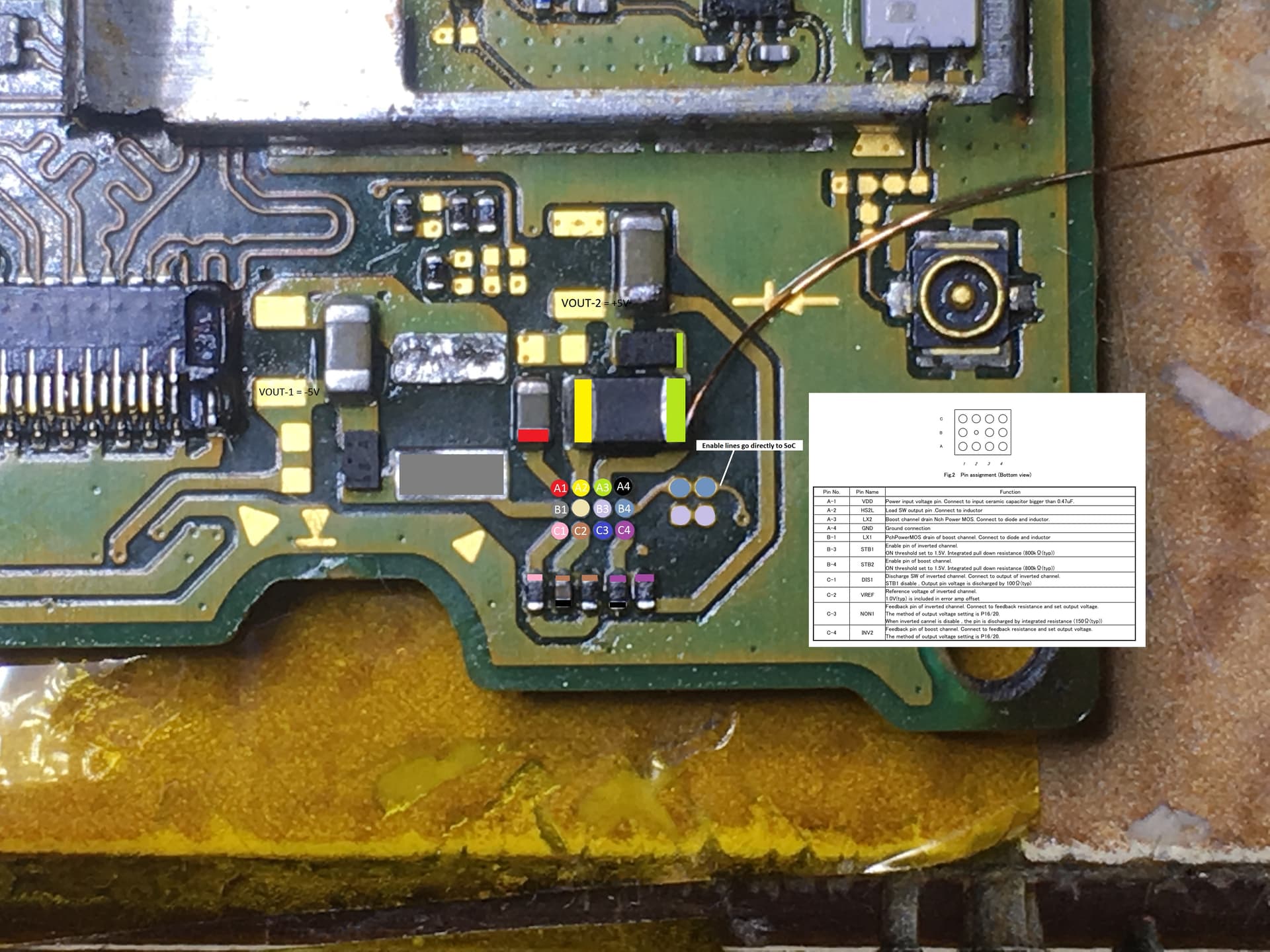
I tested everything, and comes to the 8316 IC, There is 4V at input voltage, but nothing else.
If I refer to this diagram, there is no voltage at B3 and B4.
So that means 8316 IC as nothing to do there?
But from where comes EN pins?
Assuming it is actually making it to that stage in the boot process where the 8316 is actually being told to enable it’s outputs (ie. you don’t have another issue) then could be a variety of things, afair bad passive/s (that row resistors etc just above) , if one of them was bad / open, that could cause the issue, possibly bad diode/s. Could be something dragging down the enable lines or the +5 &/or -5V rail low. or could be an SoC fault.
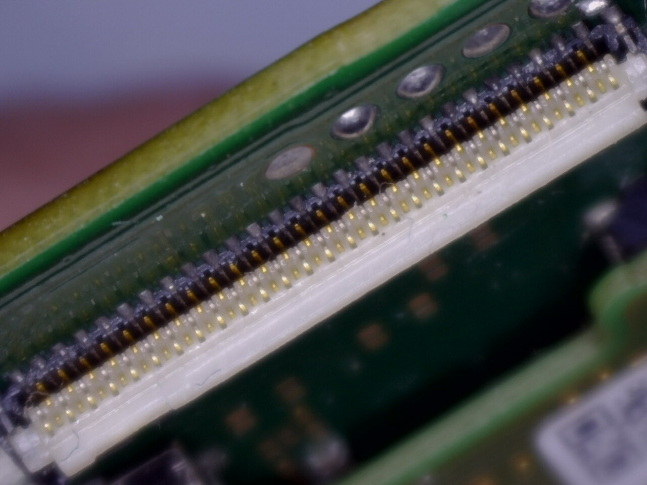
What I’d say is, make extra extra sure you have no bent pins in the LCD connector (use your phone camera in good lighting if you don’t have a microscope) in which case that will be your problem, 8316 IC/support circuitry may be faulty as a result too but worth verifying this first.
If all is fine, check those passives mentioned, if all fine then check resistance to ground on the enable line/s, check resistance to ground on the +5V rail, check the diodes aren’t open (typical) and if not then check neither are shorted out.
First thanks you very much for your help I appreciate.
Regarding the FCP connector, I changed it some months ago, flex cable has not been removed since, everything worked perfectly, so I don’t think it’s related.
Flex cable is also in a good condition.
So I have found that when I plug the battery and power the console, I have 1.8V at EN pins (B3 and B4) for around 2 seconds then it goes to 0V.
during this time I have -5V at VOUT1 and 5V at VOUT2.
That’s why I have a backlight for 2 seconds then nothing anymore.
might be a short on either of the 5V outputs, so disconnect power and check resistance to ground on the +5 rail (marked in the image above) the -5V rail is a bit tricker to measure as it will measure as a short (as it’s a negative rail)
This could be an issue elsewhere too though I’m afraid, if the above isn’t the problem then it’s a bit tricky to say as it could be a whole variety of things.
So +5V is reading huge value going down to 88kOhm after few seconds.
-5V is reading 9kOhm with black probe on ground, and almost OL with red probe on ground.