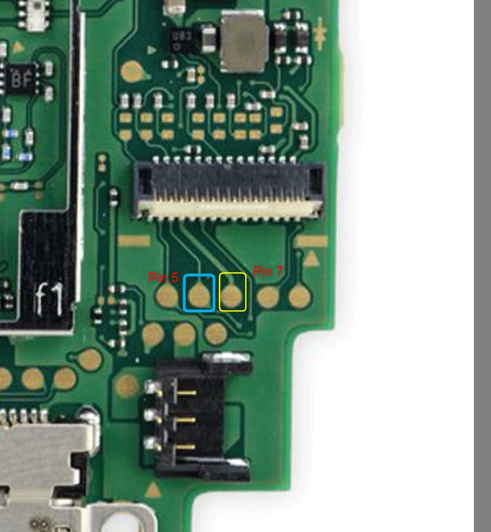
I’m running into an issue where my left joystick(connected to daughterboard) doesn’t have any left/right movement in software/calibration. I’ve tried a new joystick with no difference. I assumed maybe the ribbon cable had an issue but I confirmed continuity from the connector on the daughter board to the mainboard(its pins 5 and 7 from the right on the daughter board and the same from the left on the main board). I also confirmed continuity to from each connector to test points on the board.
These traces seem to lead to vias that disappear into the board somewhere I don’t know where to look next.
has anyone ran into a similar issue or know where those traces may lead?
What’s your resistance to ground on the pins connected to the joycon inputs? I’ve had some button / d-pad issues that i traced back to the stm chip on the opposite side of the board.
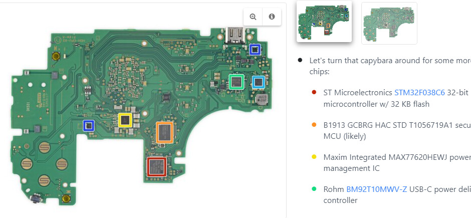
its the chip highlighted in red in the photo.
pin 5 from the left is about 2 Mohms and pin 7 from the left is about 2 Mohms. I’ve been trying to use the balika011 site to follow the traces but some of the traces on the site aren’t complete… and difficult to follow.
gotcha, 2Mohms is definitely looking to be ok, if those pins were showing signs of super low resistance id be looking hard at the STM chip. If you can highlight the pads for me, I can see if I can help trace. I imagine your losing the line up near the north side of the board where it curves?
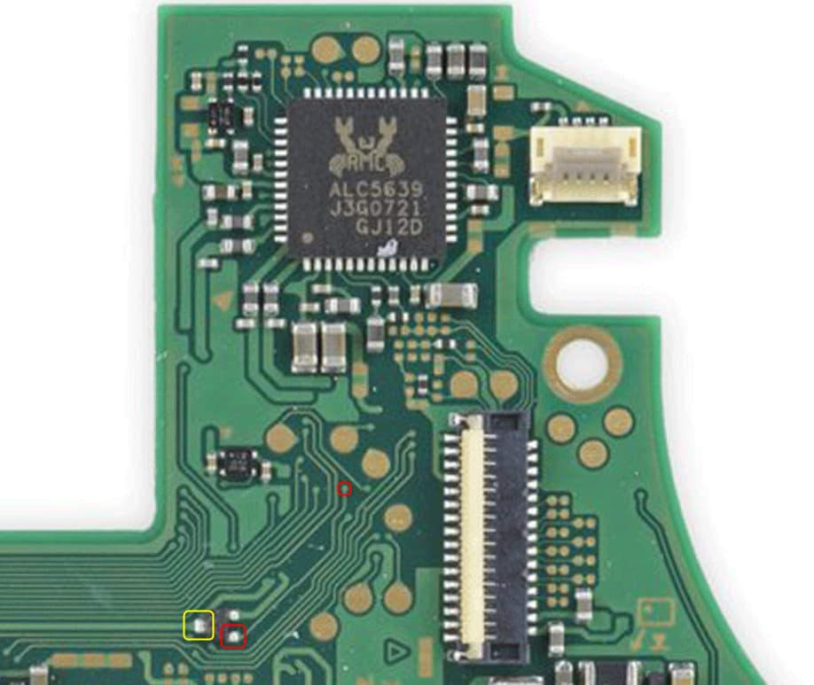
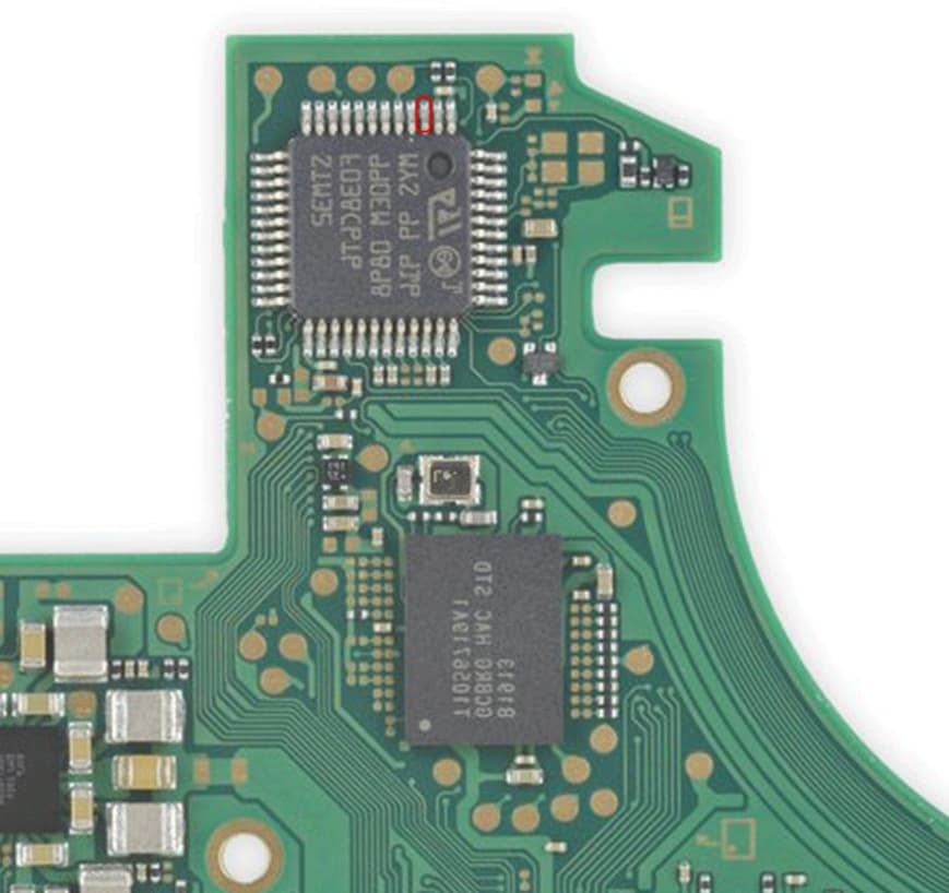
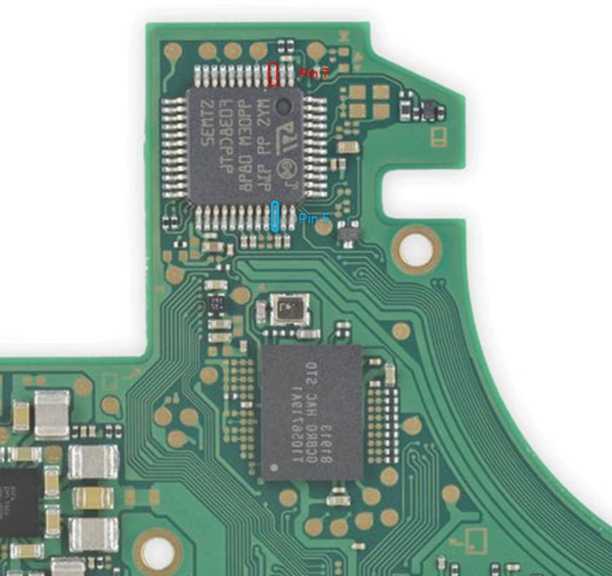
I was able to trace pin 7 to a small transistor(assumption) yellow square in the image. This goes through the layers to the highlighted pin in red on the second image. I’m wondering if maybe the transistor isn’t functioning properly, but the diode readings seem ok. I may swap it out and see if that makes a difference; seems easy enough so I’m not second guessing it.
looks like the top leg of the transistor goes to the tiny chip directly above it in the first image. Flipping back and forth through the layers of this board is starting to give me a headache… lol
pin 5 is still somewhat of a mystery since those traces disappear in views on the site.
I’ve got to say, so far this switch lite has been one heck of a learning experience. So far i’ve replaced M92 and the backlight IC and of course fixing other mess ups during the process.
Everything now works except the left/right on the left joystick… this is the last hurdle…
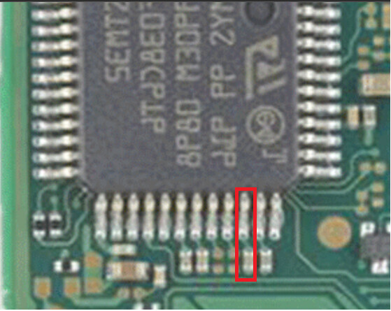
I would buzz out the test pad for pin 5 and the leg / passive highlighted in red here. I do believe this would be pin 5. Are you sure you identified the second pin (pin 7) correctly? Going through the layers here it doesn’t feel like its the right one as it doesn’t end up going to the STM chip.
1 Like
Sorry for the delay; wasn’t allowed to post anymore yesterday; had to wait 20hrs.
I can confirm continuity from pin 5 to the leg you have highlighted.
regarding pin 7, I have continuity from pin7 to the single leg of the transistor, then continuity from the bottom leg on the other side of the transistor to the pin I highlighted in my second image.
based on that, it looks like both pins end up at this chip.
Wanted to document the above for anyone that may need it in the future.
I’m not sure how exactly, but I managed to fix the issue. I replaced the transistor from a donor board and when reassembling, the latch on the daughter board ribbon connector(main board side) broke so I ended up replacing the connector.
Once I got it back together it was working. I’m not sure which fixed it, but I’m leaning more toward the connector not putting enough pressure on the ribbon cable. My guess is testing put just enough pressure to make connection.
@coda Thanks for your help on this one! ![]()
No problem. I would put money on the connector as well, they’re pretty famous for causing many headaches on these boards. That one in particular is a real PITA. Glad ya got it working though!
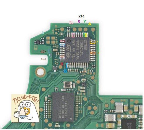
Upload here for reference if anyone needs. Dpads pinout to the STM32 MCU
1 Like