I have a first gen Switch which died with no prior symptom. After playing with it, hibernated it with the power button and it never switched on again. We had it checked at the local Nintendo service, they said motherboard failure and proposed getting a new device. So I took investigation to my own hands. I proceeded according to this thread:
Fuse OK.
Leaving it plugged in, the battery charges.
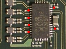
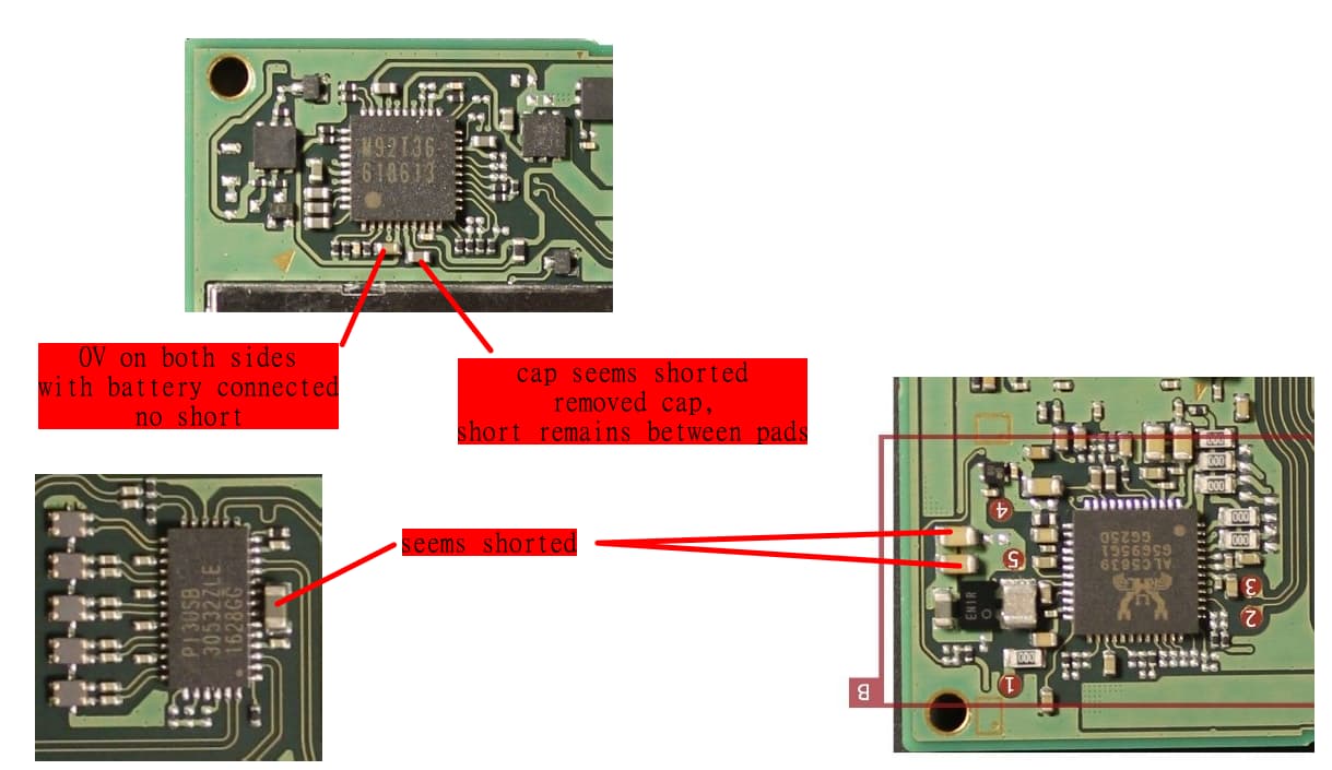
Checked the caps near the M92T36 and the PI3USB, found the following:
(will post it as a reply, the forum engine doesn’t allow me to upload pictures or post decent links)
The cap at pin 5 seemed shorted so I removed it, but the short remained between the pins. The fat cap above the PI3USB is also shorted. Also found two shorted caps next to the ENIR chip. The caps at BQ are OK.
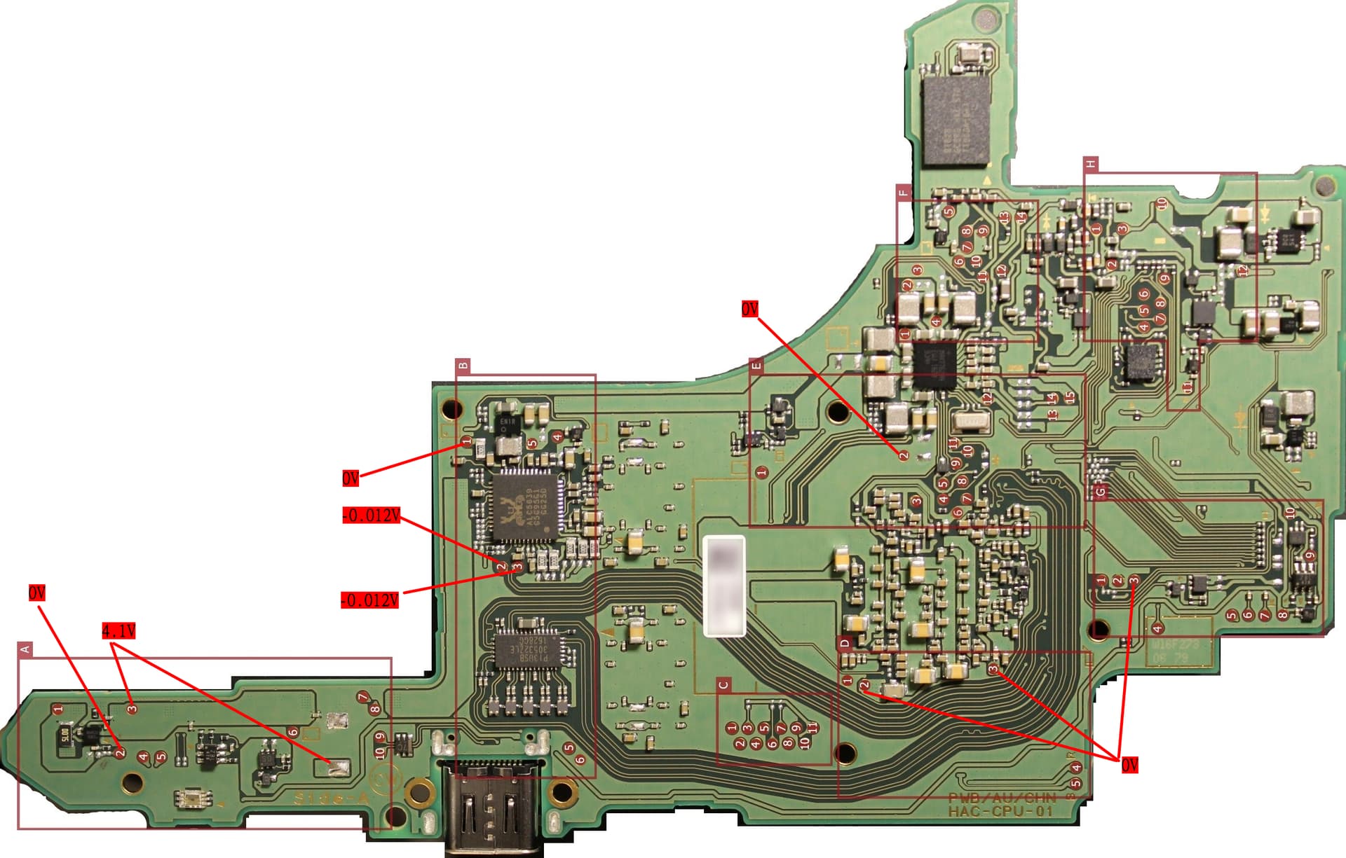
I measured voltages at some testpads according to
https://switchbrew.org/wiki/Testpads
here are the results:
(will post it as a reply, the forum engine doesn’t allow me to upload pictures or post decent links)
First I thought it will be the M92, but after seeing this thread: www.gbatemp.net/threads/nintendo-switch-repair-no-turning-on-motherboard-help.621118/
with the same sympthoms, I started to doubt. Where should I start? I live in a less fortunate country in Europe so getting spare parts take either quite some time or money, so I’d like to ask for your experience to avoid unnecessary effort and cost.
The big cap at pin 5 m92t36 ic is connected to the big cap over the pi3usb ic on the backside.
I would desolder the pi3usb and check if the short gone.
pin5 cap should have 3.3v when charging working or 4~5v when battery unplugged.
pin6 cap is on same line where big cap at bottom of pi3usb as well as the 2x22uF cap next to ENXX step-down ic.
Remove pi3usb chip and check if those short gone.
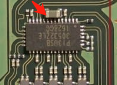
FYI, its normal having 0v reading using official 15v charger at the D+,d- test point, (next to the ALC audio chip from your highlight)
BTW, when states something is charging, please try provide voltage and current draw at the same time,(i.e 5v0.4A or 15v0.4A )ect.
I desoldered the PI3USB. Unfortunately the shorts are still there.
I stated it charges because I measured the battery voltage before and after leaving it on charger for an hour. I don’t really know what’s the easiest way to measure current draw. Do you modify a USB C cable and hook up the 5V wire to a lab PSU? Or is there a better way?
could be from anywhere since its 3.3v line, goes to most ICs around the board, voltage injection and thermal cam or old faction “Awe thumb”/alcohol test is the way to go
No, you inject 1v~3.3v(less is better since you don’t know what got short) to pi3 big cap area, not pin5 on M92T, pin5 of m925 is not 3.3v line neither, pin5 is output line where pin6 is input.
Check the datasheet and don’t misunderstand pin5 or pin6
I guess I need a VDD pin for the PI3USB. According to it’s datasheet, it has several of them, connected to these tiny caps:
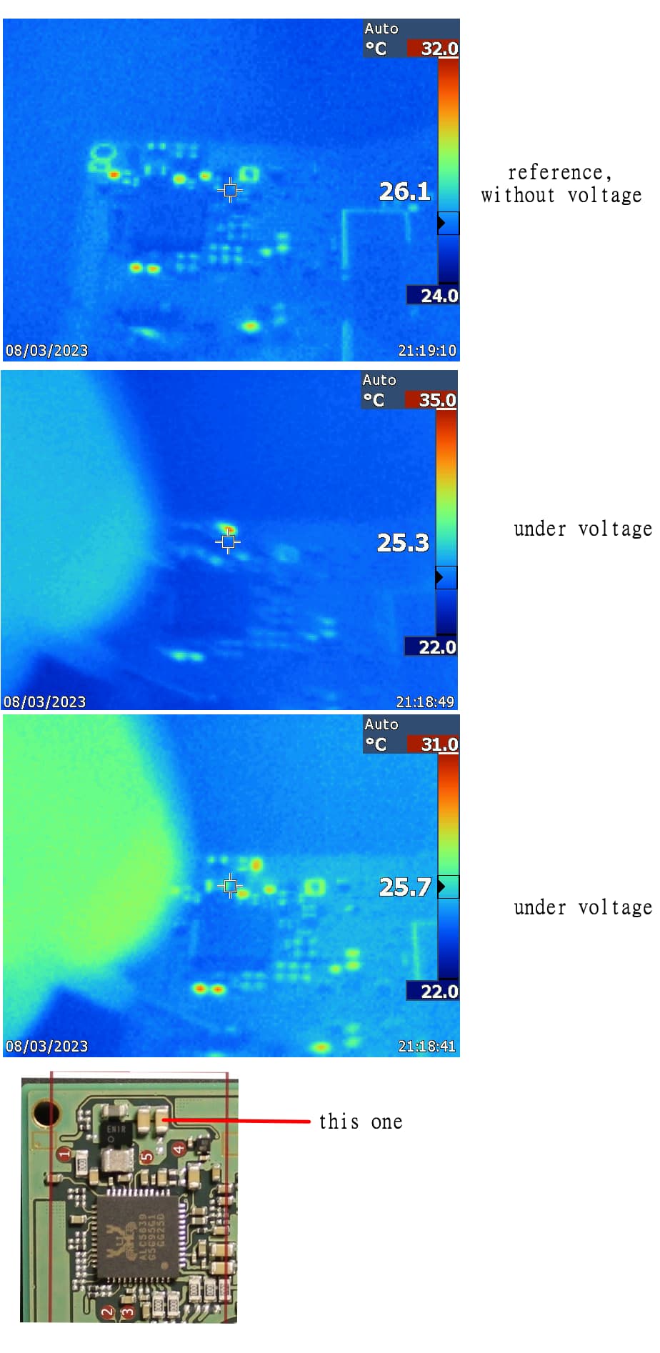
Isn’t there a safer point to inject voltage? Maybe a testpad or a bigger cap somewhere? I managed to borrow a thermal cam, now I just need a test point.
And since I can now upload pictures, here are the original ones:
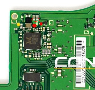
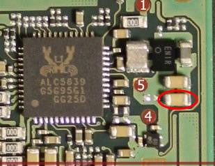
Looks like I found the culprit. The power supply cut the current instantly but I could see it flash up for a second. This was the only component to do so. I’ll desolder it and we’ll see.
Great, I desoldered that cap and the shorts disappeared from the cap at the PI3USB and also at M92T36 pin 6. But when I reconnect the battery I still don’t have 3.3V. Injected voltage appears at the 3.3V testpoint near ENXX. Nothing gets hot.
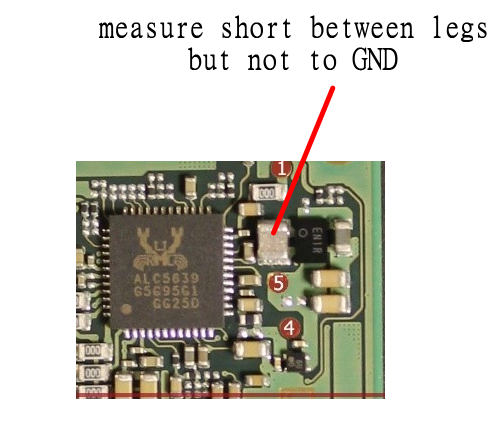
One thing I noticed is that this component measures short between its legs, but not to ground. I couldn’t find what this is, maybe it’s normal.
I guess the removed PI3USB and those 2 caps doesn’t influence not having 3.3V when turned on from battery. What else could be the issue?
The EN chip generates 3.3v, so if you don’t have 3.3v my next step would be replacing that.
Maybe it died since that cap next to it was shorted to ground and it pulled more power that it can provide.
That “shorted” component is an inductor, so it’s normal to have continuity.