No, you inject 1v~3.3v(less is better since you don’t know what got short) to pi3 big cap area, not pin5 on M92T, pin5 of m925 is not 3.3v line neither, pin5 is output line where pin6 is input.
Check the datasheet and don’t misunderstand pin5 or pin6
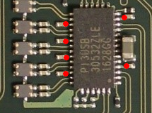
I guess I need a VDD pin for the PI3USB. According to it’s datasheet, it has several of them, connected to these tiny caps:
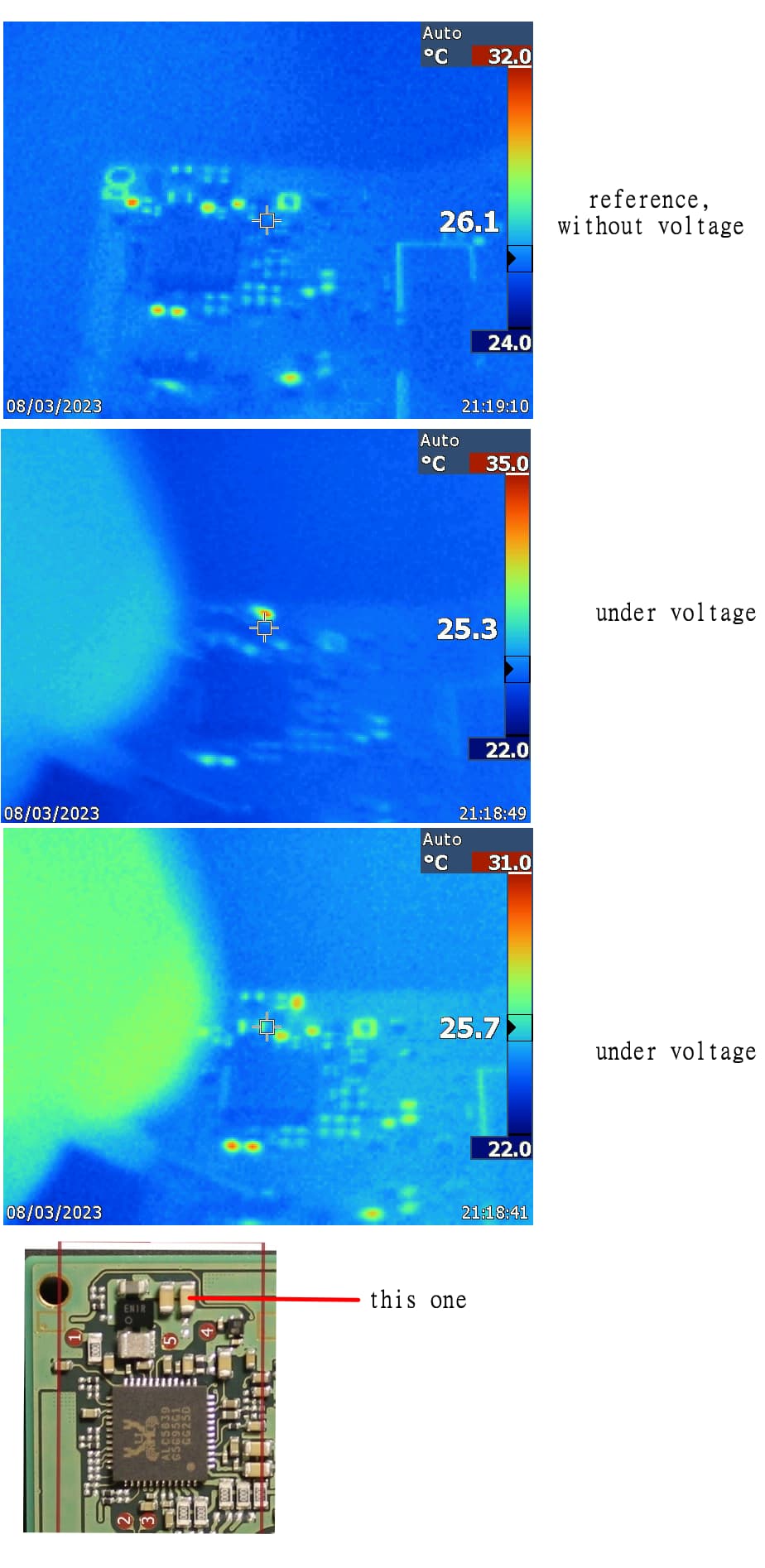
Isn’t there a safer point to inject voltage? Maybe a testpad or a bigger cap somewhere? I managed to borrow a thermal cam, now I just need a test point.
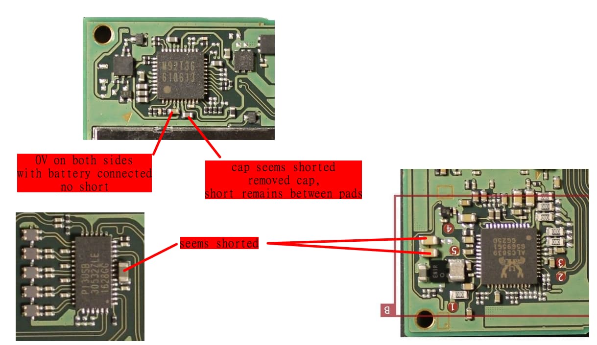
And since I can now upload pictures, here are the original ones:
Maybe at these caps? The 2 red points should be 3.3V, I don’t know if they are on the rail or something else.
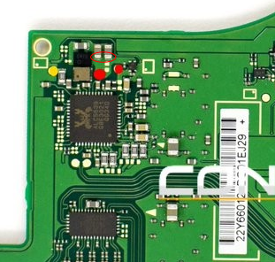
LEFT red dot is on 3.3v line but not the right red dot. you can inject voltage on the left dot but myself prefer the big cap at pi3usb ic
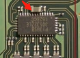
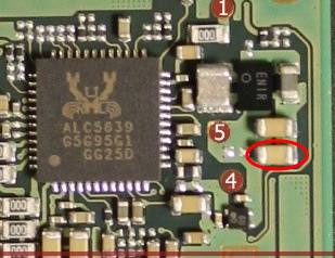
Looks like I found the culprit. The power supply cut the current instantly but I could see it flash up for a second. This was the only component to do so. I’ll desolder it and we’ll see.
Great, I desoldered that cap and the shorts disappeared from the cap at the PI3USB and also at M92T36 pin 6. But when I reconnect the battery I still don’t have 3.3V. Injected voltage appears at the 3.3V testpoint near ENXX. Nothing gets hot.
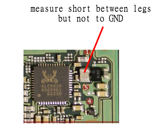
One thing I noticed is that this component measures short between its legs, but not to ground. I couldn’t find what this is, maybe it’s normal.
I guess the removed PI3USB and those 2 caps doesn’t influence not having 3.3V when turned on from battery. What else could be the issue?
The EN chip generates 3.3v, so if you don’t have 3.3v my next step would be replacing that.
Maybe it died since that cap next to it was shorted to ground and it pulled more power that it can provide.
That “shorted” component is an inductor, so it’s normal to have continuity.
1 Like
Do you know the type and brand of that chip?
RP602Z330C is the ENxx chip
Thanks. If you can tell me the value and rating of this cap as well, I’ll order them along with a new PI3USB.
22uF 4v or up voltage rates should be good
if your not getting the 3.3V rail being produced (following clearing the short) by the EN IC you should first check if it’s even being enabled following a prompt to boot (you can searcg the forum for this) if it’s not then you likely have something else causing a halt prior to this… You should verify all this before bothering / attempting to replace the EN IC. As a guess, your M92 IC is probaly bad and/or soldering and I’d start there, I’d also verify there is ono USB issues too. Also, save yourself the effort for now and just leave the P13 and the cap off for now as they won’t have any impact on boot throughout testing and verifying other issues with the board.
I was lucky, not having 3.3V was my fault. So far I was only testing with battery, with USB it’s there.
So, what I have at the moment:
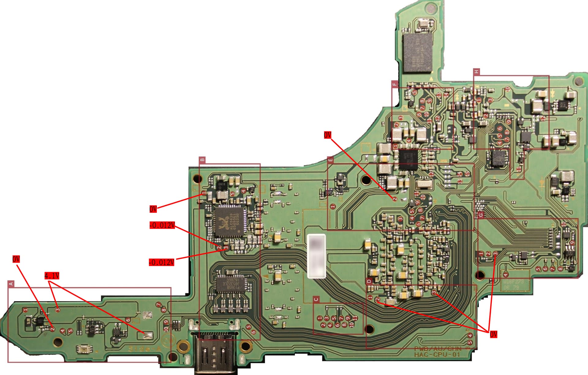
No shorts on 3.3V line, voltage at PI3USB big cap and M92T36 pin5 (3.281V) and pin 6 (3.291V).
I have all the 1.8Vs according to this one.
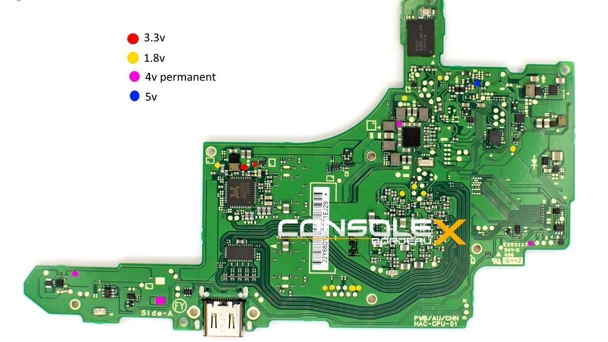
I don’t have the 5V on the blue point though. (nothing else is connected, just the battery)
it will be present with battery only too you just have to make sure it’s prompted to boot (and the battery is charged enough) ![]()
Disregard that image it’s basically worthless. Who knows what blue is from that image… maybe a 5Vrail for LCD ![]() which you wont get if it’s not getting to that stage in the boot process.
which you wont get if it’s not getting to that stage in the boot process.
What is your charge current since getting your 3V3PDR back?
I don’t have a USB ampmeter, I’ll try to hack a cable together for measurement.
1 Like
33 mA from a 5V phone charger (4.7V actual voltage) for the board without anything connected.
80-90mA from the same supply with battery connected, pulling the voltage down to 4.4V.
assuming no other shorts present on the board (SYS for example) this current draw would suggest it’s booting. Connect up a known good display and see if you get anything. If nothing or if you don’t have a known good display then hookup the speakers, ensure console is booted and not in sleep, put volume up (keep pressing) tap the digitizer and see if you can hear the clicks through the speakers while unlocking.
Also might be worthwhile prior to all this taking a very close look at the LCD connector as beginners almost always bend the pins here. Use your phone camera zoomed in with good lighting if you don’t have a microscope
Just to add to this - Based on your info above I’ve made the assumption in my above reply that when your saying 33mA you actually mean 330mA (IE: 0.33A) as this would be typical aproximate current draw on a switch with no battery connected… likewise when you say 90mA I assume you mean 900mA (0.9A)… but let me know if this is not the case.
No, it’s 90.
However, we’re making progress. Connected back everything except the card reader and the jack and booted and it starts! Minor problem is that touch input doesn’t work. Note that PI3USB, cap at ENXX and M92T36 pin 6 are still not soldered back, even though I don’t think it matters. Also, left joycon was recognized, right not yet, but they are probably totally drained so I’m charging them now.
I didn’t see damage on the LCD cable.
Can you take a snap of your meter reading this? I’m guessing it;s dropping the digit or it’s down to the meters mode as it doesn’t make sense for it to be 90mA based on your previous replies. Either that or your manner of measurings is off. If you turn the console off and then connect the USB I imagine you’ll see it start at 0.33/0.4 and then jump to 0.9 (and this is in Amps)
just a guess but probably relates to the GC PCB, check the connector on the flex and see if it’s warped, if it is bend it back gently