Hi all, got this from eBay to practice on. Looks like previous repair attempts were made. USB port intact and not replaced and tests good. M92 was shorted so replaced and I can now charge a battery but it won’t turn on. FPC connectors and ribbon cables are perfect and have not been worked on. I know the fuel gauge chip can stop the console from turning on but where else can I look? There are no shorts on M92, BQ or PI3USB and looking through the thermal cam doesn’t give any clues. Bar replacing P13USB as a test, I’m a bit stuck at this point!
If there are no shorts around the usual contenders I would first check for shorts or low readings on the main rails coming from the PMIC as well as the SYS rail. I dont have a picture of it to hand, but measuring at the coils around it, black probe on ground, I would expect roughly:
5k - 10k at the top left one,
100k+ at the top left one,
50 at the ones on the left,
1k at the one bottom left.
SYS rail is measured at the R2R coil by the USB and should be in the Megaohms, but all over the place.
If all those seem fine, I would tend to try and connect it to a PC at this point just to see what it does.
If it goes into RCM mode with the emmc connected, I would check for auto-rcm if it is exploitable.
If it does so and it’s not exploitable I would check for damage to the emmc module or connector.
If it doesn’t go into RCM automatically, I would try to prompt it to do so either with a jig, or by removing the emmc. If it doesn’t connect to a PC even with the emmc removed, then I would start at the USB port, making sure everything connects where you would expect, and has expected reading from a breakout board (espesially the data + and - lines).
If it is picked up by a PC, I would run hetake if possible, and see if it reports any problems. If it is not exploitable then it get trickier, and I would end up here asking for hints 
Wow, thanks for the in depth response! Appreciated. Will have a look through all this and report back.
Ok, so here are the results.
4.3 M Ohm R2R Coil
PMIC Area
Top Right 4.6k
Top Left Starts in the M Ohm and keeps rising
50 at the ones on the left
1k at the one bottom left
Just plugged into the PC to check but doesn’t connect with EMMC. It does connect without and it is picked up as APX, I’ve installed the drivers.
Ok cool, I guess next step is to try and inject Hetake, if that works we can look for errors etc.
Thanks, never looked in to it so will try in a few hours when back at my desk 
Unfortunately, this Switch is a patched model 
What are the next steps?
Hmm, not sure. When you say it charges, do you get the battery icon on the screen? Do you have an ammeter? What current does it draw when charging?
0.48a @ 5v
No battery icon on the screen. This is with a known good screen etc.
Is that with the Nintendo charger or just a random one?
I am somewhat at the edge of my knowledge on narrowing it down at this point and am hoping @Severence will join in, but I would double check all the joins around your new M92 to start with.
My understanding is that if BQ was bad you wouldn’t get any charge at all, and that with a good M92 and the official charger you should get 15v.
That said, all you have here is a console that is not booting, it doesn’t HAVE to be a charging issue at this point. If that’s a standard non-nintendo charger I would only expect 5v anyway. The fuel gauge can prevent boot, but so can a damaged emmc, or faulty voltage regulator.
Unless someone else chimes in, my next step would probably be to go round the board with a microscope or something and check for any tiny chips or cracks on all the tiny BGA chips as they are very fragile. I would also test for voltage at all the voltage regulators around the board.
emmc wise, I think all you can safely do is get an sdcard adapter so you can connect it to a PC and see if it is detected and the partitions visible. You dont want to swap them between consoles.
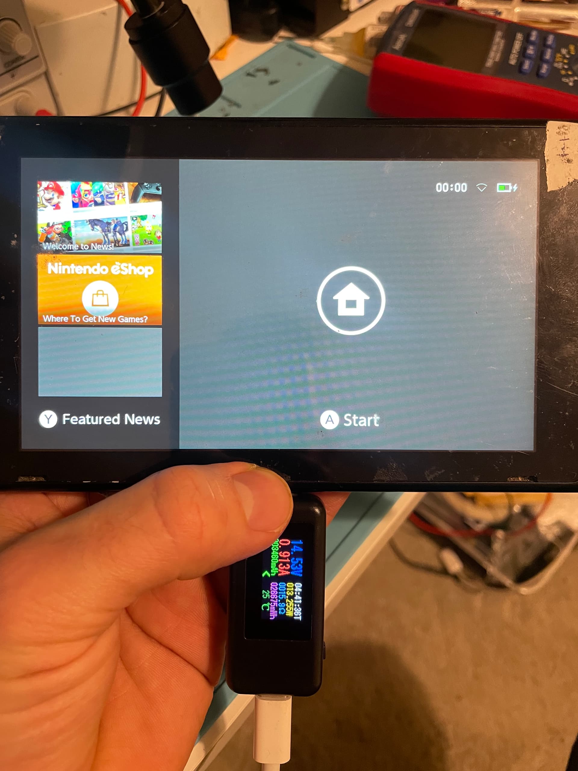
Thanks @Insomniac I should have updated this last night as I spent a bit more time on it. I couldn’t find anything wrong anywhere but realised that 5v @ 0.48a was not great so I went ahead and swapped the fuel gauge IC. I then connected power and the battery and still had 5v @ 0.4a and then the USB C power meter flickered and swapped to 5v @ 1.4a  Popped it back together and it booted Although without backlight so that’s the next step.
I’m getting OL on one end of this cap and resistor. All other measurements are good. Swap backlgiht driver IC?
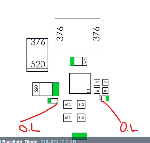
Nice! Yeah, I would replace the BL IC.
Looks the same part as the Switch Lite?
I would think so, but I dont know for sure.
I think these are the ones I used:
1 Like
Lost the cap and resistor while swapping the IC Any chance you know the values of these?
Success! Found the cap and it measured as 0.1uf, probably 25v.
Then found the datasheet and example schematic. It suggested that the lost resistor I needed was the 63.4k ohm one. I couldn’t find that one exactly but did have a 62k ohm one which has done the job!
All booted up and screen on. Lots of little cosmetic issues to sort now and a proper test but looking good. Thanks for all your help. I’ve learned loads.
Yay! good job! Glad I could help
1 Like