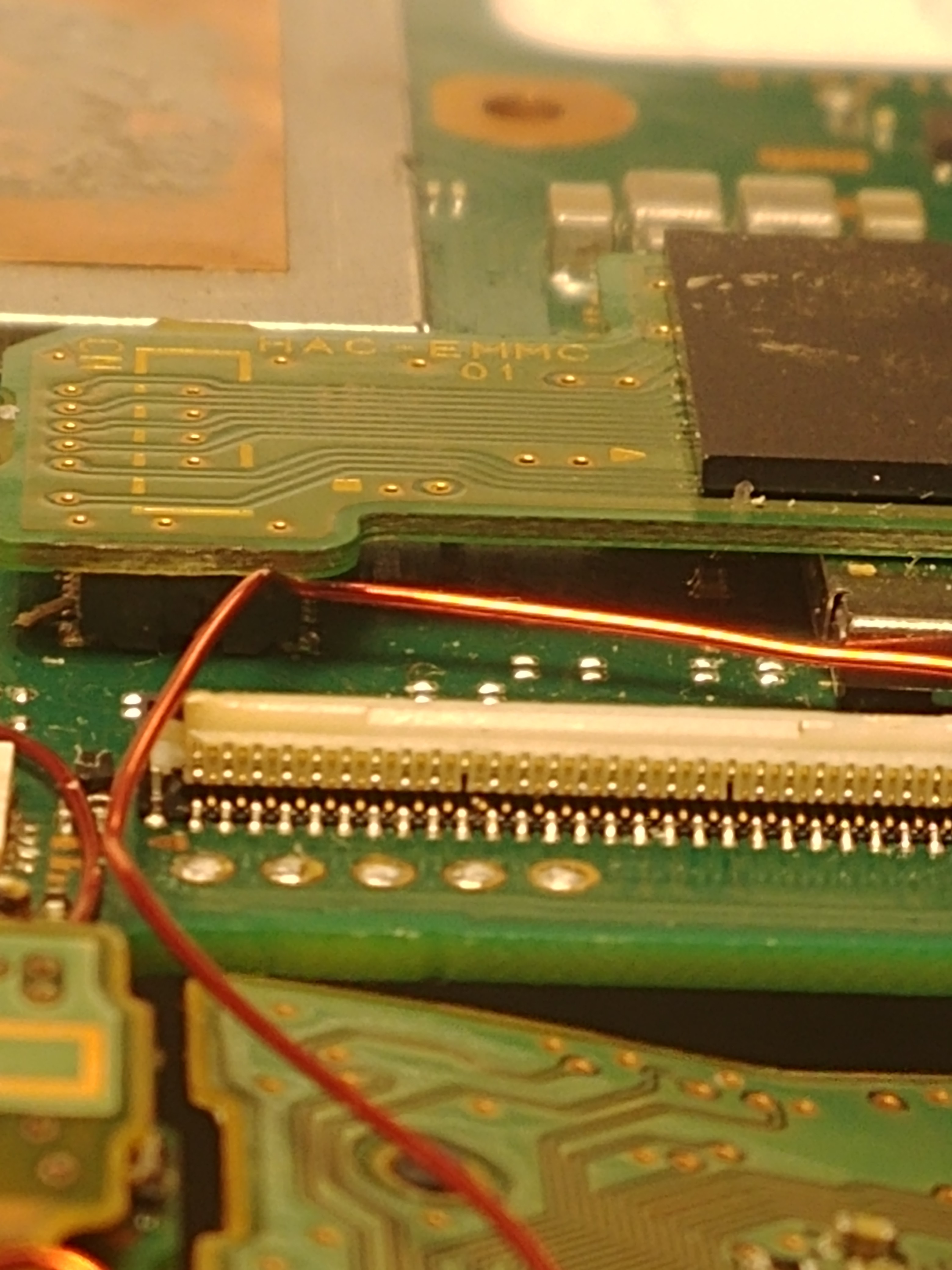
Lookit. Top row has at least two missing pins. The one in the middle of the pic you can see sitting between two bottom ones… Not at all where it should be. I bet anything we are getting shorts here or broken connections in here.
I can easily replace chips but Ive had issues with plastic parts. Not looking forward to trying to swap this
I would replace them rather that trying to fix that many pins. You need to heat the board from the bottom so you dont melt it, luckily there is nothing plastic on the back of the board up there.
For removal you could heat from the top, but you would need to protect the other ones nearby. Alternatively you could mix in some leaded solder or low melt solder before heating to lower the temperature. I haven’t had too many issues removing them myself through, so maybe more air flow and a bigger nozzle would help?
Hey there, thanks so much for replying and going back to see what’s going on. Heating from underneath at about 470c and absolutely lowest airflow is what works for me. I’ve replaced the connector and at first it seemed to be normal and the glitching was gone but then it came back. After looking at the pins of the new connector it turns out one of the pins again was jacked up, mind you this connector was a perfectly donor. I think I’m bend down one of the pins on accident when sliding in the ribbon cable so perhaps my soldering placement of the connector is a bit too “forward”. Anyways I think we may have found out issue :).
I usually go top and protect just like you say to remove but I was trying to get a feel for heating under it soldering… Im terrified one of the components on bottom will fall off. I tried this on a donor board not one of the ones Im fixing.
This has been eating my lunch for a while. I think we are on to something… Thank you for confirming you have similar going on.
Also, as suspected bending the pins was not successful. It “could” be done I got them real close to back into place with an xacto but you cant see that inside so a certain amount of luck would be involved.
I think the damage is occuring when the ribbon cable is forced in too much when not quite aligned. Also it likes to bunch up side to side so its no longer as flat as it should be. It can get so warped ive had to squeeze it flat again.
Just be extra careful when slotting it. it needs to slide in kind of easy. Ive done it at least 50 times without damage, but I def broke one of these because it worked a day or so prior before swapping pi3usb
I have taken to plugging in the lcd while it is not in the case yet. It makes getting the usb past the plastic harder, but I only have to do that once everything else is working 100%. Its the angle of the cable as it curves round that makes it such a pain as it wants to move higher up.
Totally. you cant just slip it in all nice the shape of MB makes it impossible without being rid of that middle portion. Its working if you plug it in first?
There is a small plastic “leg” near the USB that makes it tricky to get in, and you rick splitting the case above the USB. But, given that testing the board often involve re-attaching the screen multiple times, I would put the LCD cable in first, while its not in place, and then just not bother getting the USB in place until its all working. Then you only have one fitting where any of that matters.
If your really having trouble with the LCD ribbon and connector I’d suggest just practicing with a donor board, once you’ve done it a few times you won’t fear bending a pin going forward, it’s really not all that difficult, just pull the ribbon back with a fingertip, line it up and it should just slide in with virtually no pressure (provided the connector is not gummed up for some reason) if you feel any resistance just back it out and try again, remember the pins can’t bend if you don’t force the ribbon in, if your finding it’s not sliding in easily for whatever reason (flux residue in the connector for example) just put a drop of IPA on the connector which will act as a temporary lubricant
Only mention this as it’s all to easy to catch the fragile fuel gauge on the zinc frame slotting the ribbon into the connector without board out the frame or tugging the LCD ribbon side to side which could damage those bonded contacts at the LCD side