Haha I suppose it would steady your hand ![]()
Hey there, quick update on the switch. I believe it’s been fixed. Haven’t seen any flickering since I’ve replaced the LCD connector as well as a cap on the other side of the board, directly under the FPC connector. Have you soldered on a replacement onto yours yet?
No, time and money in short supply.
This is great news though. I hope to order them in a week or two.
I have parts on the way and I finally invested in a cheap microscope with a screen. Ill know for sure in a week or two.
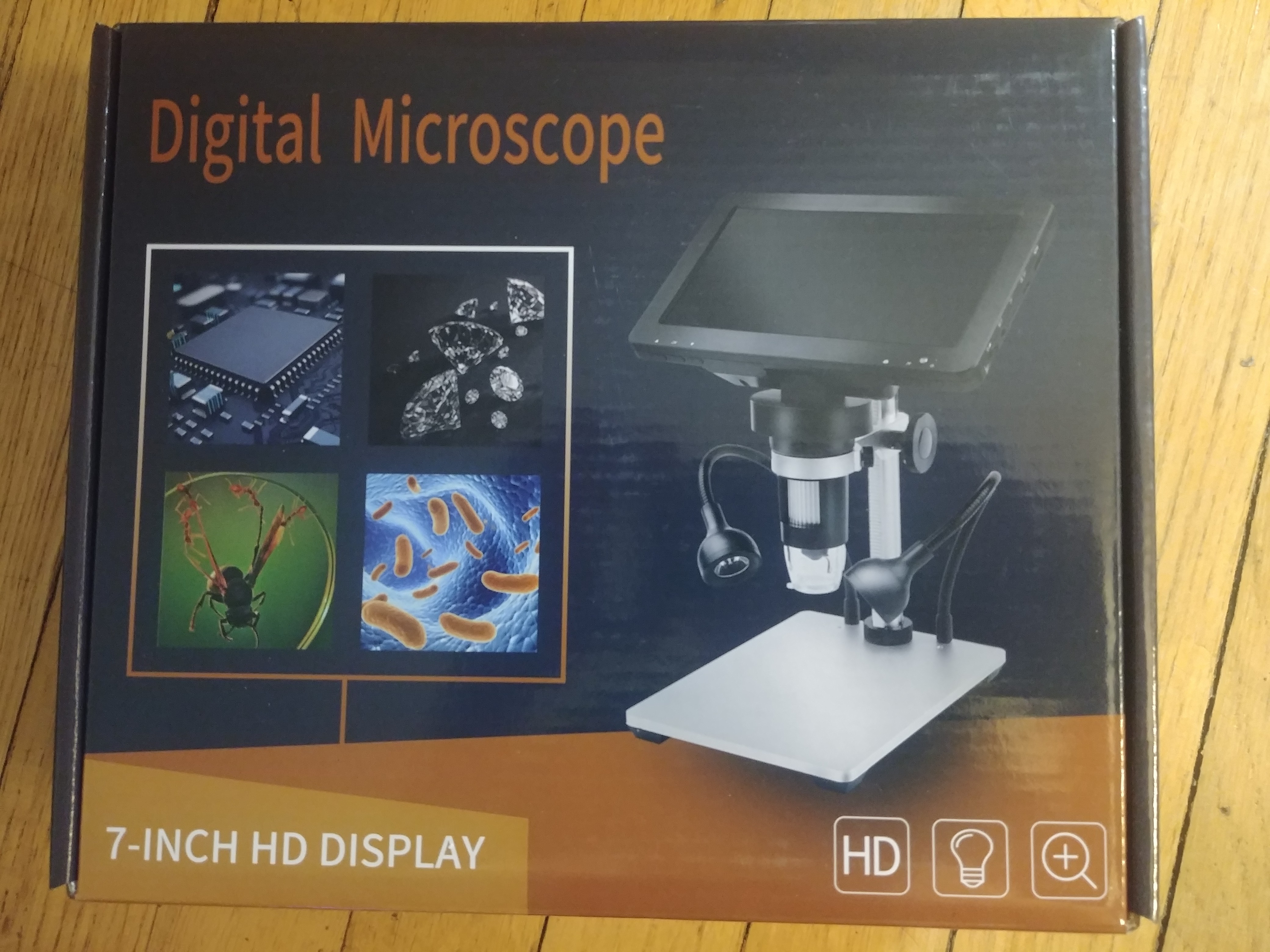
When i started to work on those consoles, i took this Microscope which was the cheapest one i found that had a HDMI output so that i could wire it on a screen :
https : // www . amazon . fr/gp/product/B08B8KS7LC/ref=ppx_yo_dt_b_search_asin_title?ie=UTF8&psc=1
I took this LED lamp to adapt it to the lens and get extra light (the one embedded in the lens is really weak) :
https:// www . amazon . fr/gp/product/B011BGH2YI/ref=ppx_yo_dt_b_search_asin_title?ie=UTF8&psc=1
and finally i disassembled the device and mounted on a mobile arm such as this one, the hole for microphone is exactly the same size as the lens of the microscope :
https : // www . amazon . fr/gp/product/B08C5631JL/ref=ppx_yo_dt_b_search_asin_title?ie=UTF8&psc=1
I don’t know how cheap is the microscope you took, but that was the cheapest “fast” (not aliexpress weeks of shipping time) one i could find. If it can help
By the way, i also once damaged the LCD connector in my first attempts, i noticed that TheCod3r is always putting back this LCD connector before putting the motherboard in the case, to have an extra flexibility outside the case. Since i do that, i haven’t damaged a single connector anymore and feel much more confident when reassembling the console. Extra information, as mentioned in one of my thread by Insomniac and confirmed by Severence also, the components won’t fall off when applying heat from beneath because of surface tension which will keep everything in place, unless you apply way too much air flow or knock-off the board while doing it. I applied this technique on 3 LCD connectors so far, and it worked well.
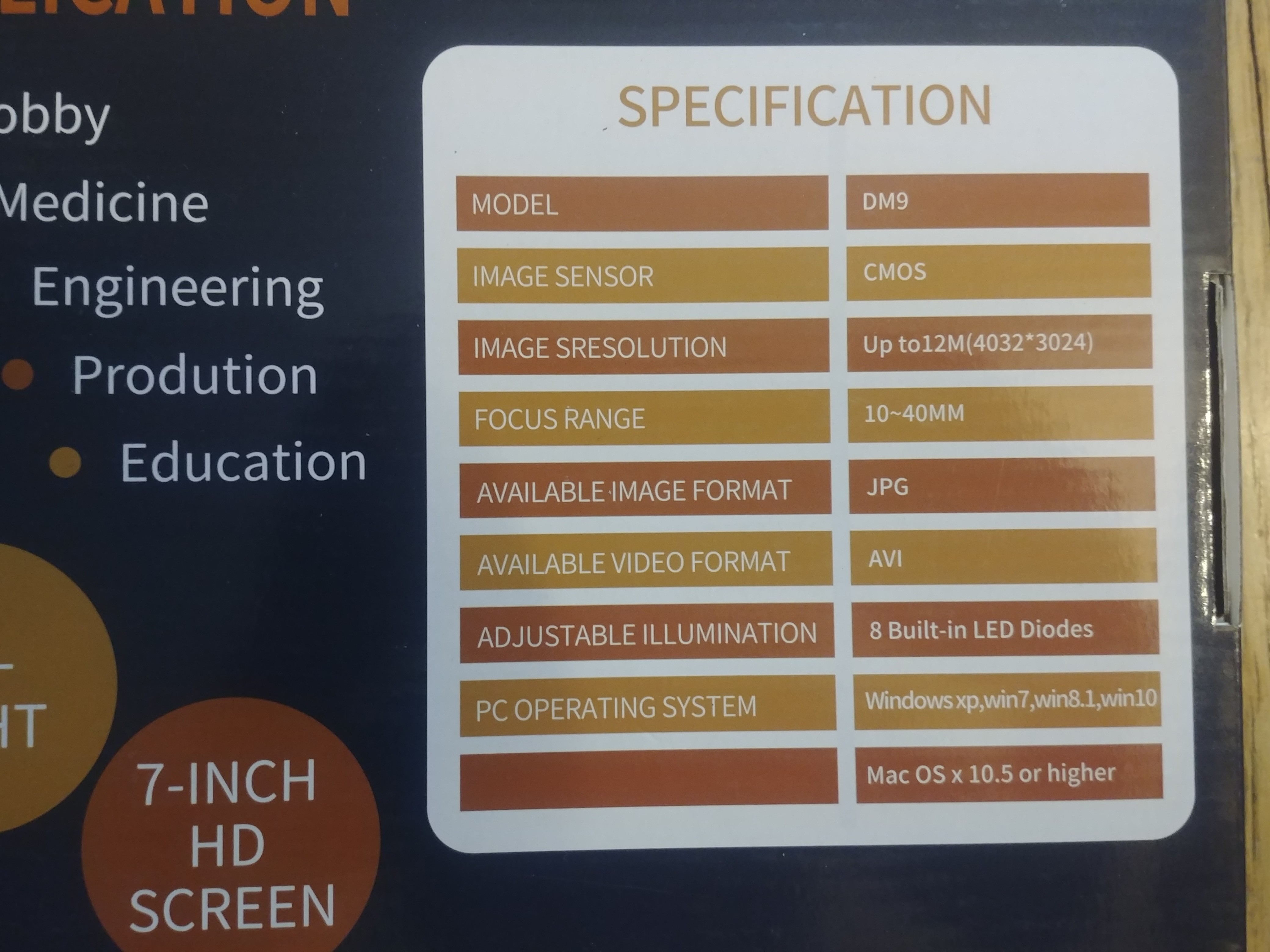
I appreciate all the info and advice. It was $100 for x1200 zoom with 7inch screen, LED lighting, lion battery and video out. Im in love with it. Amazon.
I really wanted it to have its own display.
Yeah, 100% agreed on video out capability. 100$ is really a good price, mine is definitely more expensive. Amazon . com ?
I plan on also using it on my extensive diamond collection.
Okay, I don’t have an extensive diamond collection… but that box has inspired me.
I wonder if I can see individual covids with it? lol
 maybe … you should try, how knows what you will find out Basically it looks pretty much like mine in terms of characteristics, does it have HDMI or USB output ?
USB output.
I was impressed with the usb quality feed. Looks like parts come on Mondayish
Nope.
Swapped out the LCD connector with my fancy microscope. Issues STILL present. Looks to be deeper issue than LCD connector.
I will say that the tips in this thread for attaching LCD connector without damage are VERY handy. A little IPA makes it slide in.
Ive fixed everything but this issue. It may just not be portable anymore. Always stuck to tv.
Im REALLY disappointed. I thought for sure this would clean it up.
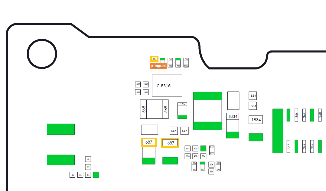
This threads pretty long at this point so don’t recall if I covered it, but I would check your getting your +/- 5V rails at the 8316 IC, if you search the forum for “8316” you should be able to find a few posts by me covering where and what to check etc
If the original cause was bent pins then there is a pretty good chance the 8316 IC, or one of the two diodes has failed which as a result will mean no +/- 5V rails and in turn no picture on the LCD 
I never did focus in on that area. Will check it out.
take a look at the following thread as your issue sounds similar
Severence, I need your help.
Would it be possible to take this to email o as not to gunk up thread?
I just need some clairfication on measuring the resistance. Im getting all manor of odd readings on my meter.
fullcircleembedded @ gmail . com
I dont think you get these "1834"s unless the LCD ribbon is connected. This is normal on a board that is not attached to screen?
Also Im not clear on how to check the diodes
I can’t really help you with Calvins diode mode reading charts as I don’t typically test/mesure using diode mode, but I’m pretty confident he would have taken those readings with the board out of assembly etc and if your readings on that rail (with red probe on ground) isn’t in the ballpark it points to issues with the diode/IC
Sorry bud there is not much I can tell you which I didn’t already cover in that other topic. your basically just wanting to check and see if the diodes have failed open or closed by measuring across them in resistance, so, one probe on one side of the diode and the other probe on the other side, as these are surface mount diodes you’ll have a hard time probing the diode pads directly (or risk damaging the diode/s) so you’ll want to use the next nearest neighbour pad/component for probing. after you’ve done this, note your reading, switch your probes round (red where black was and black where red was) and note the reading again and post them both here, you may find in one polarity the reading will fluctuate, don’t worry about this, if the -5V diode is open then the IC will have died too, so will be a case of replacing both