I managed to install a Picofly and it does glitch. However, it started with video artifacts and now displays no image. The backlight still turns on. I also see a very small spark and a slight sizzle sound at the FPC connector for the screen when it powers on.
Is there a short somewhere? Is the connector damaged or does the screen need replacing?
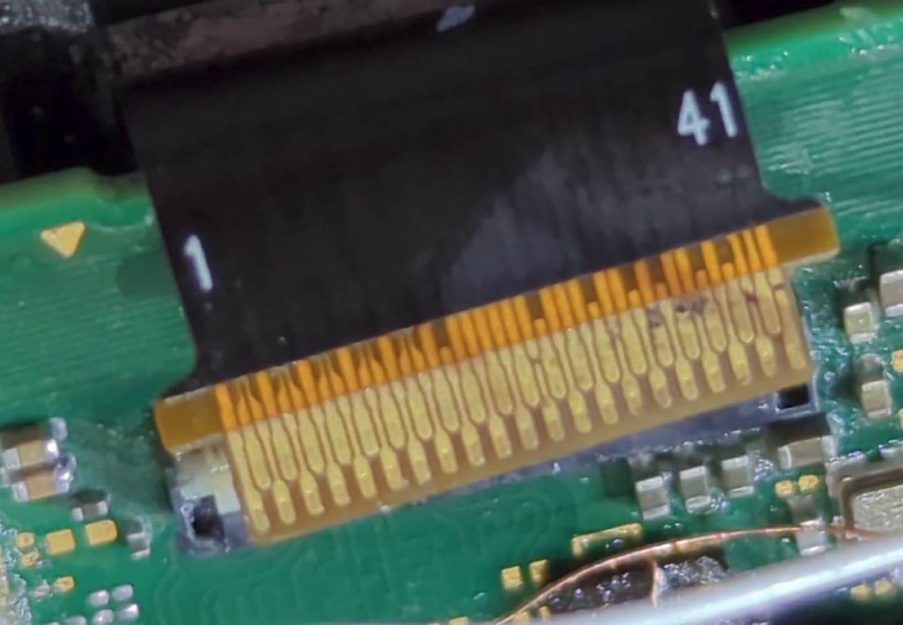
I seems that you lost six contacts at the lcd ribbon. And I’m sure there is a bent pin inside the connector.
I would check the dark spots for continuity. And look inside the connector and check for bent pins.
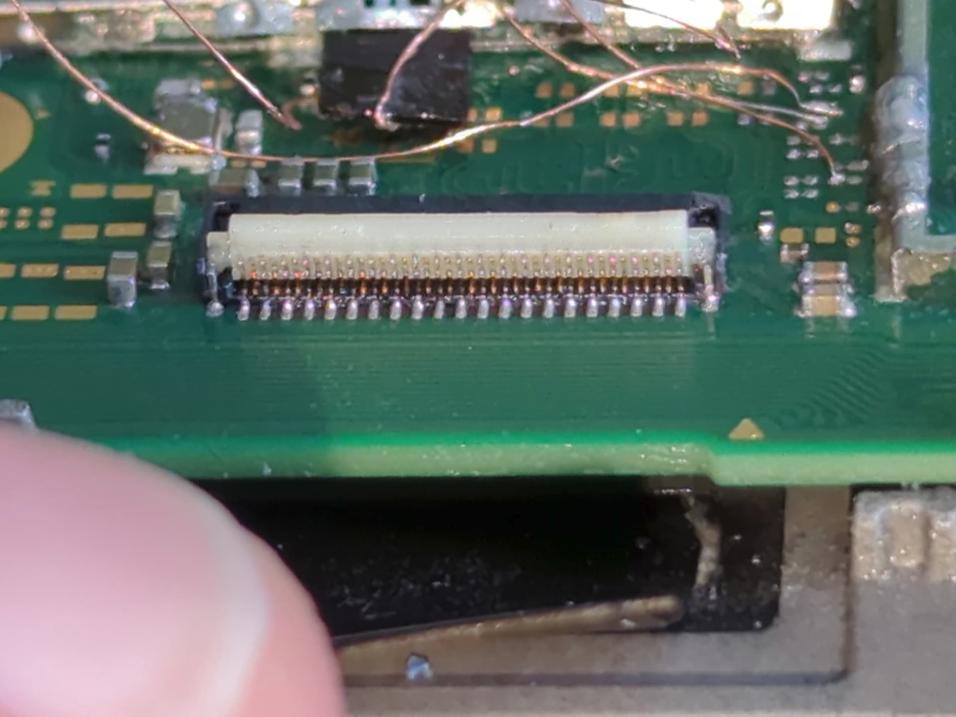
Not the best picture since I don’t have a microscope, but here is what the connector looks like. It didn’t seem like there were any bent pins. Now that I look at it, could it have been caused by flux or alcohol?
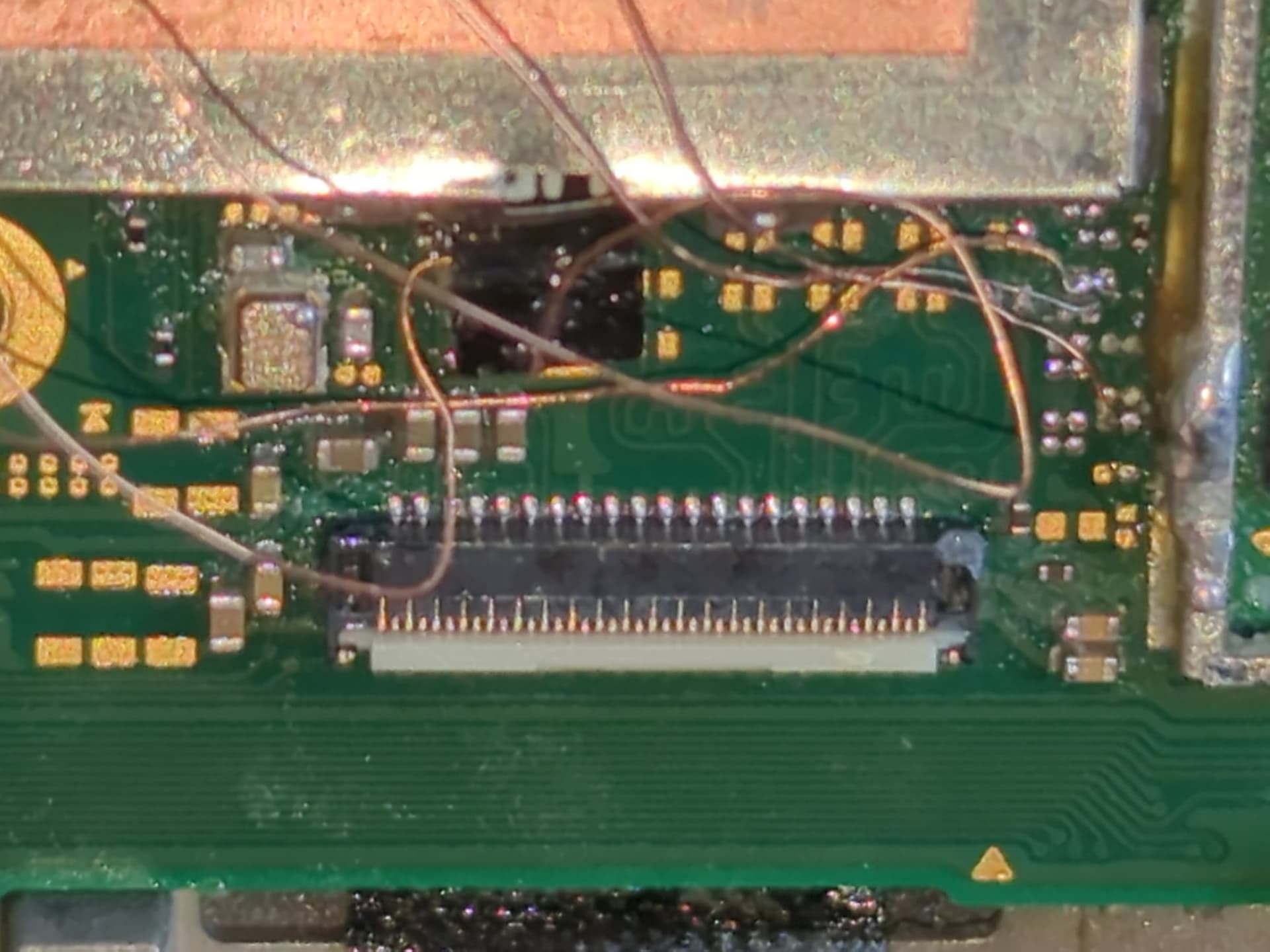
Just a few observations. Your wiring seems a bit birds nest like, try making these wires only as long as you need them to be and no more. Try to avoid crossing lines over each other whenever possible to avoid intereference. Try routing wires in such a way that they are touching the board (ideally over a ground plane) but not touching components (again interference) . Looking at your solder joints they do seem a little cold.
None of the above would cause your issues mind you and is purely constructive criticism
No, IPA and flux are non conductive, that being said, old flux which remains is the perfect attractor of contaminents - so a stray bit of solder spatter stuck to the flux could have cause your issues.
Looking at your image of the ribbon, it does look like some of the lines have burnt out, absolutely repairable with some fine enamel wire (enamel wire from some old earphone cable is usually perfect for this) though I do not envy you without a microscope.
Looking at your other images, maybe it’s a trick of the light but it seems like potentially some of the enamel on your wires has been exposed, that could potentially cause the issues you’ve seen too.
If it were me, I’d remove the modification/s, I’d have a very close look inside that connector, look right up inside right to the back of it and ensure there is no charring/burning (pay very special attention to the areas which correlate with the burnt out traces on your ribbon) , then do the same thing at the back of the connector at the solder joints, if there is any indiicators of damage then I’d replace the connector and then test the Switch board with a known good panel and see if the board is still good and go from there.
Also, to add, I’ve never used the modchip on Lite, so can you help me understand what is sticking out from the SoC shield? is this the modchip ribbon? - could potentially be touching something it ought not to be (?)
That’s the end of the ribbon cable, which I’ve bent the shielding slightly so as not to damage it. I’ll go over my soldering again later with some more wire, and then insulate that ribbon cable. The wire I’m using for the mod is 0.1mm enamelled wire, and 30AWG ribbon for the 3.3v and ground.
Thanks for the advice, though. I’ll let you know how things go alongside that LCD ribbon cable problem.