So had a look and found a few posts about not charging/not switching on posts and there’s so much info i’m getting confused So my thought here is to go through this step by step and i’ll edit this post and hopefully come up with a base guide for people to follow.
So, as above the switch i have doesn’t switch on and doesn’t show anything on screen when plugged in.
Steps
First plugged in a power meter and then into the switch. Showing 5v 0.4A. Left it plugged in for 30mins just in case but no movement.
Next I’ve opened up the console and with the battery unplugged while it charges in another switch.
Plugged in the charger and checked the voltage on the USB ports.
2 0.00V
3 000V
4 0.93
5 0.34
6 15
7 15
check caps around M92T36 and BQ24 see if any short first. then check if 5v/15v comes through fuse to these 2 IC and also check if 3.3v available on M92T36 pin5 pin6.
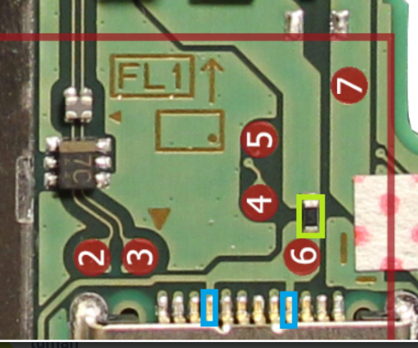
don’t really understand the numbers meaning from op. usb port pin 234567 voltage(left to right)??
Sorry forgot to post the image with those numbers will edit now.
OK so what caps am I looking for? Am I just checking continuity when looking for shorts? Which pins am I looking on the IC for the 5v/15v (guess those values depend on the charger I’m using)
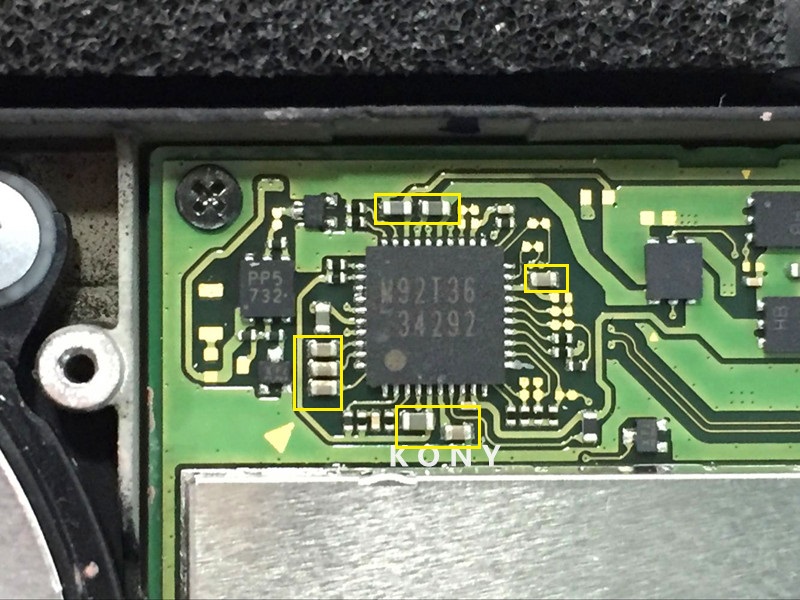
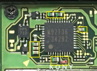
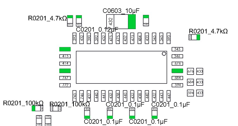
Right so this is what i’ve found
So the ones marked with Green seem to measure ok and are grounded (if that’s the term)
The one that has red grounds both sides. So i guessed that means a short of some sorts.
So digging around on the forum while looking for values of the caps/resistors etc i cam across a thread that linked this youtube that has my issue
youtu.be/EP65185uGiA?t=873
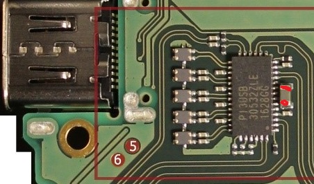
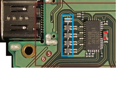
So on the other side of the board
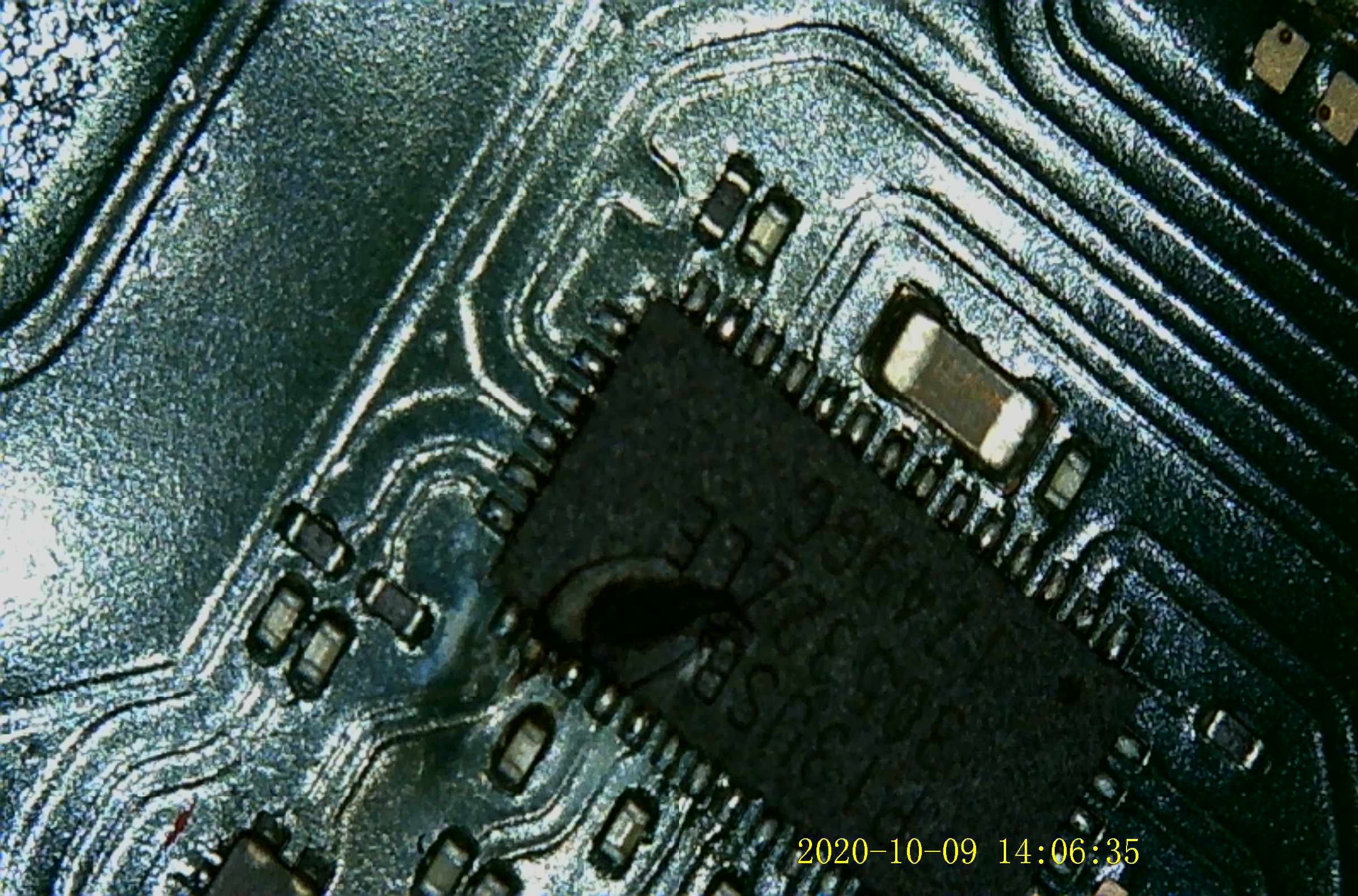
This one is also “shorted” as per the youtube video shows. So on closer inspection it looks like it the “Video” chip is damaged.
Yes, you need a new video chip. Also, be sure to check the filters after the video chip as well as sometimes they get blown out when the video chip goes bad. Another thing to keep in mind is that just because you replace the video chip doesn’t mean it will fix it. It usually will but there can be other problems as well. After you replace it you’ll want to go back and check all those caps for shorts again.
So i got the chip off but also knocked off the CAP above it.
From Calvin’s images it’s a C0603_10uf
But what’s the voltage as i can see they come in different voltage ratings on Ebay.
Contrary to popular belief, the P13USB is simply a switch to route signals down the correct pins of the USB Type-C port because of its reversibility. Signals are flipped as you flip the connector.
It’s a notoriously difficult chip to replace as it’s too easy to flood the ground pad in the middle with too much solder causing intermittent connections with the pins.
This chip getting damaged is a common cause of the 3.3v rail shorting, and you can still use the Switch in handheld mode with it removed. I’d recommend testing it before fitting another chip as there may be damage elsewhere.
Secondly, the damage you have from the pictures has most likely been caused by voltage lines getting onto signal lines on the USB Type-C. Before you waste time replacing the P13USB, you will want to thoroughly check the USB socket and charger cables for damage. Last thing you want is to fry the chip just after you replaced it because the port is still damaged!
 So my thought here is to go through this step by step and i’ll edit this post and hopefully come up with a base guide for people to follow.