Hello, I purchased a faulty OLED on eBay. The seller claimed that it had not been attempted to be repaired. However, it turned out that it was unpatched (the chip had been removed). The device does not charge and appears completely dead. I have checked the usual components and found that the CPU cap on Pin 18 of MT92 is shorted.
I removed both the MT92 and the cap, but the short circuit is still present. After that, I removed the MAX77620, but the short circuit remains. Does this indicate a problem with the CPU or the RAM?
All oleds are patched unless you mean it turned out to be a v1 switch?
Everyone calls that cap the cpu cap, however it is just a cap on that specific rail that is shared with a few locations including the cpu so it is better to refer to it as its rail, for example 1v15, 1v1, 3v3 etc
Thank you for your reply. It is an OLED for sure. I believe the previous owner installed a mod chip, but it has since been removed.
The short is no longer present after I removed MAX77812, but I’m uncertain if this is the only faulty component. Is there any way to check the condition of the CPU and RAM before I proceed with any further steps?
Other than checking the resistance of the various rails and comparing it to a working board there isn’t really a good way to tell if the apu or ram is fine.
With the short cleared you may as well replace that max ic and put a m92 back on and give the board a test
Just take a look around the nand area since installing a mod on an oled involves sticking a flex pcb portion under the nand ic
Thank you for the sugesstion. Just received the 2 MAX chips, and I have reflowed all chips back, no short when injuct on the Vsys. However, when I press the power button, the current only jump up about 10mA and then back to zero. No voltage from the MAX chips. Any sugesstion? Cheers,
I’m thinking that something perhaps went wrong with the modchip install… Have you checked the CLK point in the PCB? It’s common that people end ripping it off. Also, do you have the ability to reball the NAND? When installing modchip, after a few months the solder balls can crack, I would recommend reballing the NAND just to be sure. Good luck!
Thank for you reply. I can reball the NAND, but the previous owner did not reball the NAND, he used the adapter I belive.
I just realise the MAX77620G I bought from Mouser may not same as the Nintendo one, which is MAX77620H. No idea what is the difference. Could not find any useful info online, I have ordered a MAX77620 from Aliexpress, will see if this make difference.
I know from experience that a MAX77620H will not work in place of a MAX77620A (V1 vs V2 switch) so your MAX77620G may not be a suitable replacement.
I wouldn’t reball the nand or anything until a proper MAX77620H is soldered in
I finally received the MAX77620H and a donor board. After replacing the MAX77620H twice with the parts ordered from AliExpress, the problem persists.
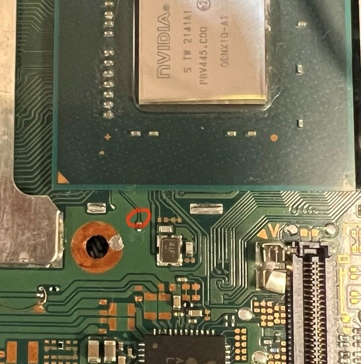
However, I did find an unusual diode reading when comparing it with the donor board at a specific position (circled in the photo). The reading is 0.12V, whereas the donor board shows 0.45V. Since this trace only goes to the SoC, I suspect that the SoC is dead
@PhynxVT, indeed, the donor board is an OLED board, according to the seller, it is unfixable, sugessting potential issue with the SoC or RAM.
@jkyoho, you are right, I had a wrong measurement on the donor board. The Donor board reading is 0.105V.
I managed to borrow a oscilliscope, and unfortunately found no CLK signal.
This weekend, I plan to attempt take some components from the donor board to further troubleshoot and diagnose the issue, but I have no idea where to start now.
Have you used an ammeter and the official charger to see what it draws as a whole?
You mentioned that the board goes to 0.10a then back to zero? is that with a bench supply?
If the board is not hanging on 0.10a (or some similar value) and instead goes back to zero (with no battery) then you should put it back in the case and connect what is needed, power button, battery, lcd etc and see if you get a battery symbol
A working board will usually go from 0.0a to a few values like 0.07a, 0.09a, 0.11a etc then back to 0.0a with no battery connected