I have checked diode measurements with a good oled and all values are similar around the right joy con circuit - ICs and components. Didn’t find any shorts at all. Confirmed the joy con rail is good and have tried different joy cons. The joy con will connect wirelessly but does not show the animation or connect when sliding into the rail.
Diode mode is useless at the best of times, and in your case all your doing is is basically checking results relative to ground / that nothing is shorted to ground but what you want to be checking is, are your joycon rail contacts continuous to the applicable connector and in turn circuit (?)
So first I’d be popping the steel “dowel” pin out the joycon rail, pulling out the contact ribbon, inspecting the contacts for signs of liquid/corrosion or any bent pins which might prevent contact, if you have that then that’s your problem, if no, then you’d connect up the ribbon to the motherboard and check that you have continuity from each pin to their respective pin at the connector (at the connectors solder joints) .
If you’ve verified all this and if your still have issues then afair, when the joycons are connected a lines is pulled low (which is what causes the connect animation) so that would be the next point of interest. You’d have to look this up, but it might be a high state lines pulled to ground (I’d guess) which might point to something being wrong in the circuit (at which point you might want to start checking voltages at the connector etc)
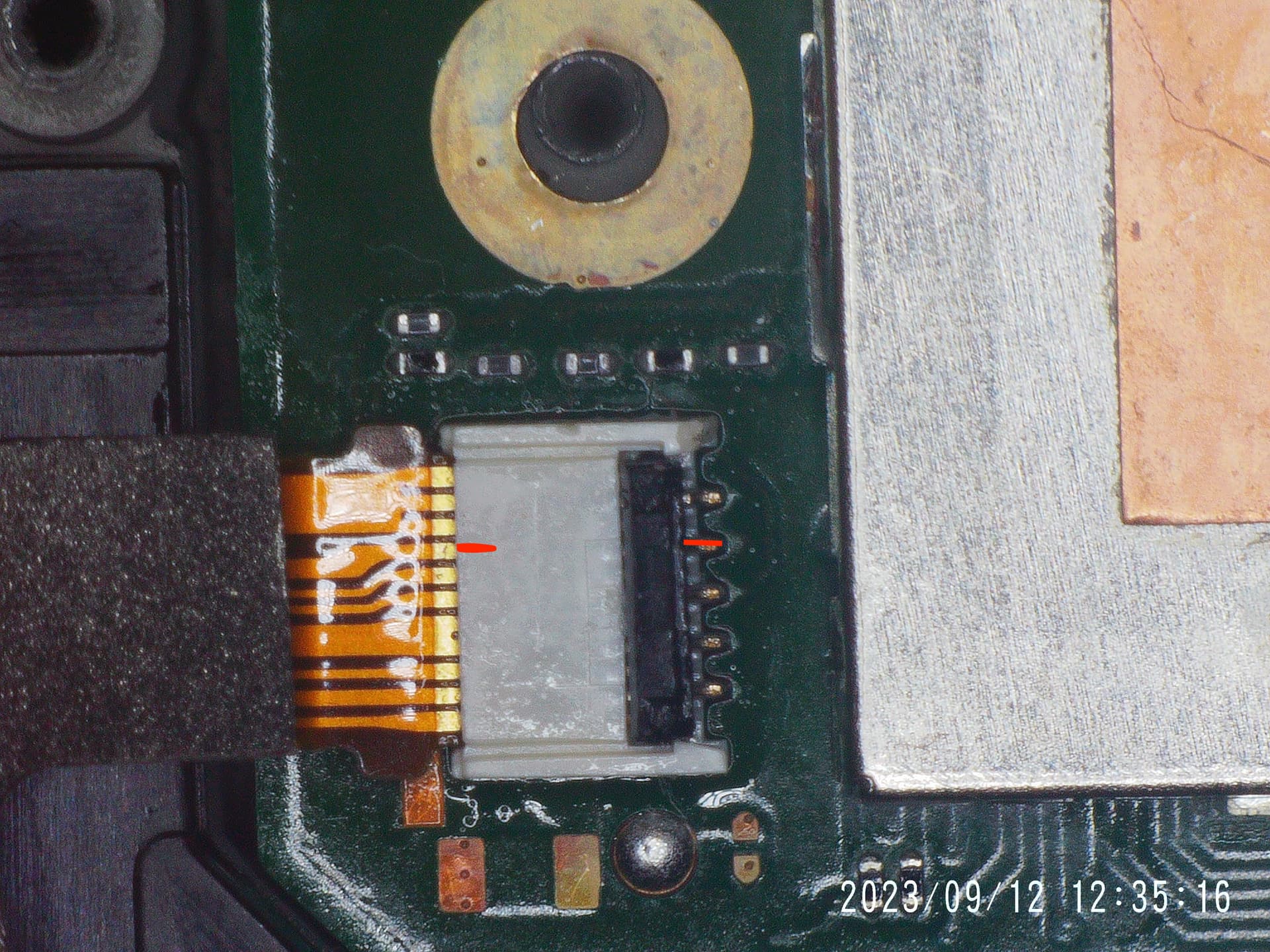
Thank you @Severence for the reply. I checked the Joycon connector and was not getting the 5V on pin 4. I found a post on another forum which led me to check for the 5v at fan connector as the joy cons share the same power circuit. Interestingly, now I wasn’t getting 5v on the left joy con either which was working fine initially. Continuity between these 3 points was good so the suggestion was to reflow MAX8969 which is boost regulator located left of the SOC and just down from the lcd connector.
After doing that, the right joy con now connects but doesn’t do the animation or sound. Left is perfect, animation and sound are there. Confirmed the right is charging so now more digging around to figure out the animation part.
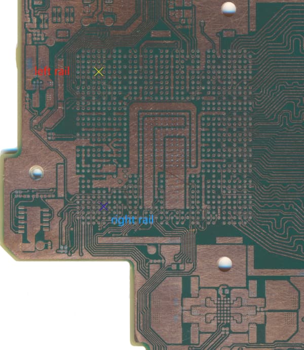
Would this be the pin 4 (which I’ve highlighted in red in my image?) this is assuming the connectors are the same, sorry I don’t have an OLED handy currently.
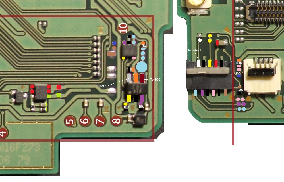
Apologies, but this image is pretty much as far as I took my analysis of the joycon circuitry (on a regular Switch rev board) … I may have went slightly further in my analysis on another topic somewhere on the forum even though this is a regular rev, the circuit (even if using different IC’s) is most likely going to be very similar on OLED
Take this with a pinch of salt, as I didn’t take the time to positively ID a lot of the components in the area (or can’t remember if I have done prior), but off the cuff, it looks like the 6-pin IC you can see on the left is potentially a mosfet, and the 5V output is likely “switched” via this, if that or any of it’s surrounding components were bad then this could potentially cause the issue. (which would explain why one joycon side doesn’t have the issue if there is a separate fet per side)
Again, pinch of salt, may not even be a mosfet, may not be switching the output etc
Regardless, might be worthwhile disconnecting battery and measuring resistance on pin 4 of the connecter relative to ground and ensure pin is not being pulled low (for some reason) and if the IC I identified is a mosfet, identify it’s gate and see if it’s high (assuming n channel) and if not, why not.
To find the potential mosfet, buzz out in continuity from the pin of JC connector on any of the IC’s in the most make sense areas
That pin 4 trace goes under the board so I will need to do the continuity check as you suggested. Think I will have to solder a wire to the connector to secure one end while I probe the backside of the board.
it kindof looks like the pinout is different but I’d guess it’s just inverted (?)
I’d buzz out from the the actual Joy con contact pins (after removing the steel dowel) and see where they are going and correlate the location at the connector just to be sure (joy con contact side has to be the same as every other switch)
This page might help
If it’s just inverted at the connector, then everything which applies on regular rev would apply here.
Notice how he say’s the following
Pin 5 (Serial data, console to Joy-Con) is normally pulled high on the console side when nothing is connected. Since this line is inverted on the Joy-Con side, it will be pulled down when a Joy-Con is attached to the console, thus initializing a handshake.
It seems Pin 5 needs to be pulled down for a while for the handshake to take place, 500ms works for me.
If the line isn’t high then you likely wouldn’t get the connect animation, and also, if it isn’t pulled low when the joy con is connected then you also wouldn’t get the connect animation. (again though, you’d have to check what pin “pin 5” correlates with on your connector as it seems like it’s potentially inverted)
Also, my mentioning of the mosfet earlier, is more relating to the potential charging issues, I don’t think based on my continuity map image that the line which is pulled high is doing so via a 5V supply (I’d guess it would be 1.8V)
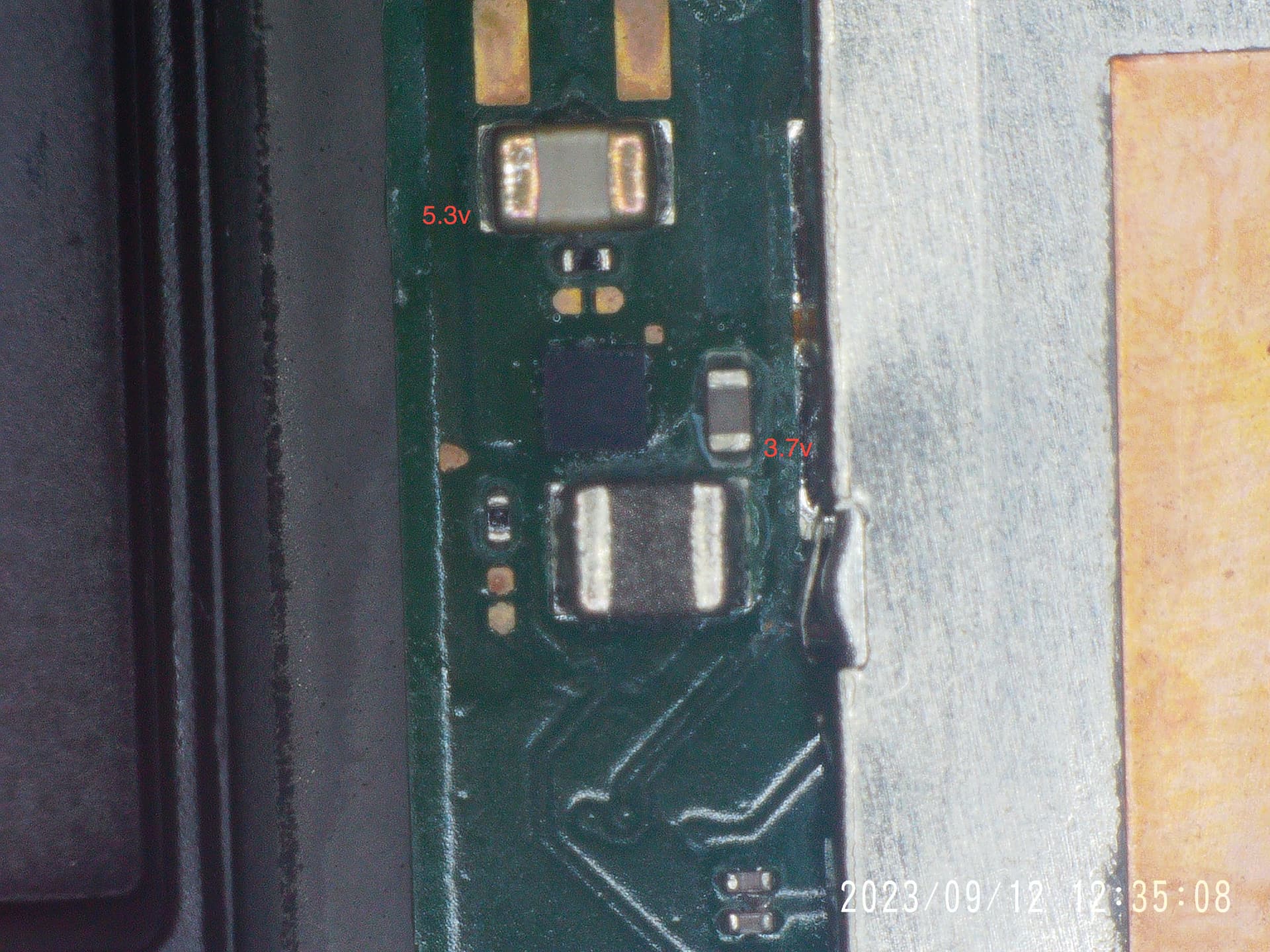
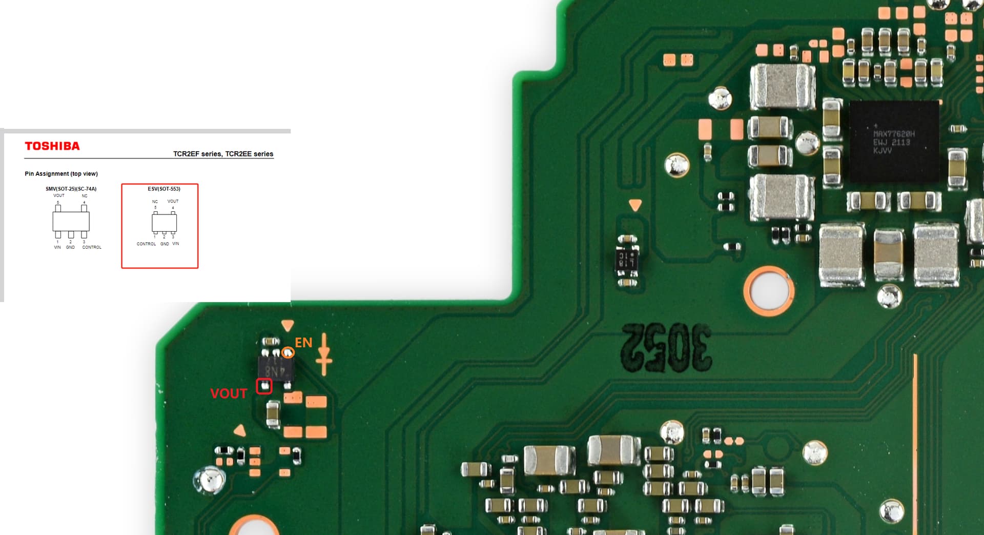
I’ve not checked, but it’s a linear reg so I’d guess it’d be on following prompt to boot, though I suppose the inverse could also be true.
Either way, just check it’s producing it’s output with joy con disconnected and if no, if the control / enable line is high as @jkyoho said, then go from there.
So I am getting 0v on the enable pin which explains why the joy con has suddenly stopped connecting again.
I was able to check with my other oled and the enable pin goes to 1.8v when a joy con is connected and 0v when not connected. Do you know where the signal comes from to enable the pin?
What is the purpose of the regulator (?) does it provide charging voltage to the joycons or is it for something else.(?) does something else have to be in a known state for this regulators enable to become high (?) I genuinely don’t know,
All questions I’d be asking myself (and determining by buzzing out from the IC in question and then cross correlating that back to the joycon pins and using that git page as reference) prior to thinking about going anywhere near the SoC.
My continuity map in my image earler would be the start of this (for example)
You could measure the enable lines resistance to ground in both polarities and compare to a known good too to likely verify a NC issue also.