So for some reason the switch refuses to output anything more than 480p when its in docked mode, checked all wires and my dock both are working fine. In the tv resolutions menu its there are only 2 options auto and 480p. Is there a fix for this
Due to that pi3usb is outputing dp (display port) signals, I would guess there is a problem with the docking station. Did you test another docking station?
This one is pretty typical on poorly soldered PI3 IC’s, with USB pointing down it’s the pins on PI3 right hand sand if I remember right.
Of course, USB or filter problems could cause issues (though I don’t think this issue specifically)
Yes the dock is fine nothing wrong with it
I believe the usb should be ok as i connected it with a usb c to usb a cable and the connection worked fine. Is there a way i can check the filter
If the dock is working fine with another Switch, @Severence approach should fit.
The pi3usb ic is a little sqeamish. The signals are there, otherewise the dock wouldn’t display anything.
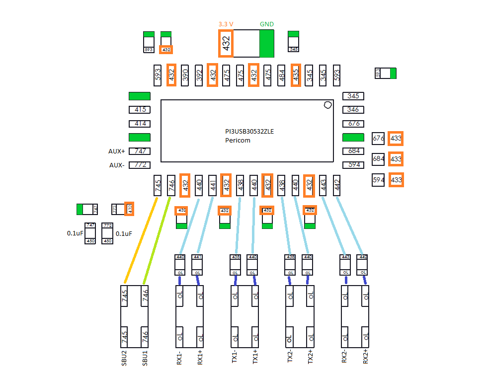
From my point of view, I would look for a unstable signal line. The lines to the five filters are pairs. You can check in resistance or diode mode if the values (blue lines) are very similar and the filters top to down for continuity and no cross talk left to right.
I understand is there any reason why the p13 ic has problems cause both of you were quick to point it out
Also what about the yellow and green line what should their values be
Also also if the lines are intact and the filters are fine should i replace the p13usb ic
The dp signals which are converted in the dock to hdmi signals are here managed to pass through usb-c.
It is common that the pi3usb ic or filters are failing, one thing is for example the tiny spaces between the contacts of the usb-c, which tend to touch if the port isn’t holding the plug tight enough.
Yellow and green are the AUX lines and should have the same values. But are different to the blue lines.
I feel like i should also point out that in the switch menu it states that the only tv quality options are 480p and auto which also brings up 480, doesnt that mean that the switch knows that it has a fault, i doubt that if the connection lines were broken it would know. I feel like it should be the ic itself sending back messages to the cpu. Just thought i should state that
Also where does the signal go after the filters is it strait to the usb port?
Was the Switch used? has rework ever been done on it?
If the answer to either of the above is yes, then the fault is most likely as I said, poor soldering on the PI3 IC (on the right side pins/pads) or possibly if the two things above are not the case then it’s and/or USB/filter issues. Also possible, layer delamination due to over rework.
No, and no, bought it first hand I got how i can check the filter how can i check if the usb is ok
Check from USB breakout directly to the PI3 IC (“pads” on edge of IC) if all checks out (check in continuity but pay close attention to the actual resistance in ohms) then it’s the IC itself at fault or the board layer issues mentioned prior ![]()
Sorry kinda new to repairs so you mean i should check if the usb port has low resistance connections to the p13usb ic right?
Right, via a USB breakout board as this will rule out the USB port too (if you measure off the USB pins directly you can intefere with the result)
Exactly, you wanna make sure the path/s continuous for each respective line going to the PI3 IC and that the resistance is low… In the case of layer separation and dodgy filters the lines in question could potentially be high but still low enough to cause your meter to beep in continuity, 30 ohm for example, which would be bad ![]()
Alright i get it one last question which pins of the ic should i check for continuity to the usb breakout?
The paths going to the filters?
There is some continuity maps / diagrams floating around somehwere for this which tells you exactly but you can just check them all too and pay attention to any which don’t beep (OL) / have high resistance which would indicate the fault (specifcally relating to the IC “pads” which you can see directly connecting to the filters)
1 Like
Ok after alot longer than i should have spent oppening the switch, i finally did, and to my disappointment/confusion the pads are very very VERY tiny, which is kinda on me as i work of pc and laptops so this is kinda new to me, but what my problem is, is that i dont think my multimeter tip is gonna be able to contact 1 ic pin and its gonna be contacting 2 or 3 which will cause a problem. I think there should be thinner multi meter probes but before i go out and buy one is there anything else i can try instead