So, I have been working on another switch that among other things had a bad USB port with ripped traces. After fixed everything, the switch happily booted up and was able to charge both ways. But on initial testing with my dock I would get a back screen.
I took it apart again and checked for continuity from the port which was all good, so I gave it a good clean with IPA and a brush and tried it again while the console was open. With just the battery connected and nothing else I got an image on the dock! So I put it all back together… and black screen again. I tried a few more times putting it in and out and then when removing it the greenlight stayed on. After unplugging the dock, now it doesn’t respond to a switch being inserted at all, and doesn’t provide charge either.
So, this leave me with two questions:
What is likely to have died within the dock?
What is the likely cause on the switch end?
For 1 I would guess the M92T17, as its the chip I often see people mention.
and for 2 I would guess a bridge somewhere on the USB port. But if anyone has any insights before I get started it’s much appreciated!
Yeah, the switch is definitely the original cause, though it now doesn’t work on any of my switches so something has failed. That diode map should be a big help I will report back once I have compared!
Most of my readings are similar-ish. Though the two reading in the middle are higher on mine. The first 503 on the left if shorted to ground for me though, which seems like the bigger issue. Any idea where it leads to?
Pin 4 at the ribbon connector is line cc1 and pin 27 is line cc2. They both go to the m92t55 ic (cc1 to pin 35 and cc2 to pin 37). If one of the lines is shorted, I would expect the m92t55 is broken.
Ok, so I have ordered the chip, it will arrive in like a month, and apparently no-one here sells them.
In the meantime, any idea where to investigate on the switch itself? I figured it must be a short between vcc and one of the other pins, but I am not detecting anything having opened it up… that said last time it was open it worked and only went wrong once closed up again…
The original damage on the USB pins was entirely on the visible row, the only repair work not visible from the outside of port is a wire reconnecting the hidden vcc pad, as the front pad was missing. That does suggest its the most likely issue, but I am getting readings in the mega-ohms between vcc and the pins on either side. Do I even need that pad connected? Should I remove the port and disconnect that wire?
If you shorted vcc to the cc pins and the m92t55 is fried of that, you should test the m92t36 at the Switch if the ic is also bad now. (same pins 35 and 37). The cc lines are only able to handle up to 6V.
The both vcc lines are designed to handle together safely the ~ 1.5 A during fast charging the battery. It should be no bigger problem if one line is not present, but it doubles the stress on the remaining line.
Do you have a usb c breakout board to check the usb c pins after closed up the Switch?
Ah, good plan, I will check the M92 on the switch. I have a USB breakout, but I figured I would get odd results if the battery was connected. I haven’t removed any of the board screws etc yet, just the back cover and shield so I could get to the battery. I will put it back together and check for shorts again after I have double checked the M92.
The M92T36 appears to be fine, pins 35 and 37 have resistance to ground in the 3M region, and all the caps around it are still good. Booted it up, and it was still charging.
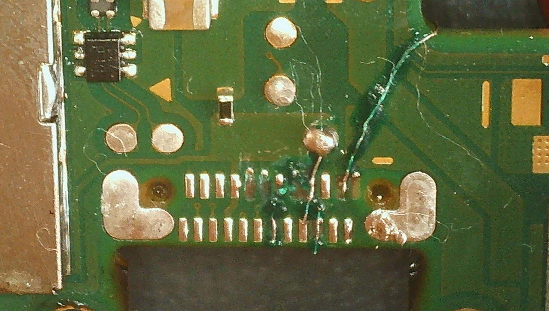
Was still unable to detect a short between vcc and any other pins so removed the port again to see what was going on. This is the state of the pads now:
Not pretty, admittedly. I think the issue may have been the pad next to vcc on top row, those 3 or 4 pins had little jumper wires going to their vias, and that one has a lot more wire running under the usb than I thought, and while it was not touching, it was pretty close. Not sure why that would have killed that line though, as I dont think that wire could have reached the line below, it wasn’t THAT long…
For me the both left ones in the top row (A11 + A12) seems to be very close. The pad B3 in the second row, is this a wire to the other side or only a little to long?
Hi Calvin
The wire on B3 connects to the via on this side, it wraps around only to provide somewhere to soldermask to try and keep it still when reflowing.
Which do you mean on the top row, one ones on the far right (going over the top of the board) or different ones? If it is those ones, they are a little close, but I didn’t bother connecting the one on the far right as it is ground, so there wouldn’t have been a wire there for it to connect with, just the little via, which I guess I should solder mask anyway to be sure.
If A11 and A12 or B3 and the housing of the usb c port are so close, maybe they are getting in contact when inserting the usb plug or tightend the screws, which would grounded the signal lines and results in no hdmi output tv.
I have now redone the port including all its tiny wires to the vias. This time I didn’t let them run under the port, and made sure both ends were visible.
I also checked for shorts between ground and all pins and vcc and all pins at multiple points as I reassembled it. And yes, it is now working! Thanks for all the help, I clearly need to test more in the future!