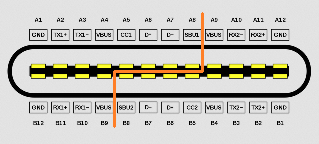
So I’m trying to figure out what signal on what pin switches the Switch from screen to TV out. I got a switch that didn’t boot and on investigation the P13USB had popped and the track under pin 22 (SBU1) had burned out.
I replaced the Pi3USB and ran a jumper from pin 22 to the filter. The Switch now boots and charges as normal however it doesn’t dock.
I have check the continuity from the USB C port to all the parts on the motherboard, using a USB-C breakout board, and this all seems fine.
I’ve check the 3v going into the Pi3USB and these are all present. I’ve checked the diode values around the Pi3USB and they all seem to be within spec.
I’ve checked the filters and these all seem good along with the caps just above them.
When I try to dock the switch the on board screen goes blank but the TV doesn’t see any signal from the dock. I’ve also tried a HDMI dongle and swapping it 180 degrees I still get nothing.
With just a 5v power supply attached I see 1.8v on pin 22 (SBU1) and with a HDMI dongle this goes to 0v and I see 3v on pin 21 (SBU2)
What I would like to know is what is the difference between a power supply and a Dock/HDMI dongle plugged in? What signals change on the USB-C port. I know the CC lines may swap but that depends on which way the power supply is plugged in.
The orange line divides the pin rows in to sides which could be connected to the plug. I m not sure which side is necessary for the dock. I will check this later.
Maybe I m wrong, but I don t think that the SBU line should be affected on the input power and vary its output. It depends on the orientation of the plug, which pin (SBU1/SBU2) is high.
Did you check the both AUX lines?
So I did a bit more today so far. I get 3v on pin 20(AUX-) and it doesn’t matter what cable or orientation I have the cable plugged in. I get 0v on pin 19 (AUX+)
When I have the 5V PSU connected I get 1.5V (varies from 1.2 to 1.9) on both pins on the filter connected to pins 21 (SBU2) and 22 (SBU1). If I swap the charger around in the USB-C same results.
When I connect the same PSU to the HDMI dongle and plug it in I get 3v on 1 pin of that filter and 0v on the other pin and if I swap the dongle 180 degrees in the charger I get 3v come up on the other pin of the filter and 0v on the other (basically swaps over).
I took the USB-C off as I wanted to check the pads and they are all good. I also swapped the M92 just in case it was something from there causing the issue but no change.
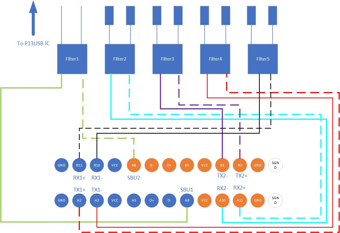
I mapped out the USB-C to Filters and you can see the results in the picture. I’m going to change the first filter to see if that makes a change.