I am interested in this as a hobby project and purchased a switch from Ebay. I know no history on it, but all I know is it does not turn on!
I have charged it from the computer, till my meter claimed it was full.
I have also:
Checked the fuse.
Checked all the caps around BQ and the coil.
I have checked the caps around M92
I have checked the cap next to the ‘USB’ chip and all of the filters next to it.
All cnnectors look good and there is no corossion on the board.
Do I need a special chager?
What can I check next?
Is there a backlight circuit that needs to be checked, if so how/where?
Does anyone in the UK know a good sorce to obtain spare parts as shipping from the US is getting very expensive.
I do not have a dock but I do have meters and an oscilloscope
I would just buy a new screen but dont want to waste money if I have missed something ‘obvious’.
Any help and guidance would be much appreciated.
Many thanks!
p.s. I am new to this - I have worked in electronics for over 20 years but on own dessigns and stuff with schematics
I am going to assume that when you say you have checked the caps, that you are measuring each side of the capacitor against ground, rather than across the cap itself. (If not, you should check them like that first).
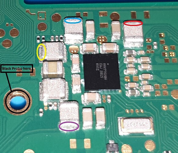
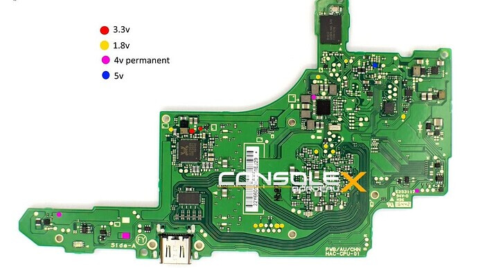
After that I would probably check the resistance to ground at all of the rails. This pic has most of them, the last one is on the large 2R2 coil by the USB port.
Yes, sorry, I have checked the caps from both ends (one at a time) to ground.
I will check the rail resistance, as soon as I can get back to the bench.
Thanks
Urrr good question. This is where I struggle a bit. We need to work out what on the 1.8v line (red, top left) is pulling it low.
Easy one to check is the eMMC, you can remove it and see if the readings improve (it should be around 5 - 10k). The M92 is also on 1.8v and can fail without any surrounding caps showing a short.
Other than that, we would need to find points on the board that are on that rail, the lowest reading can point towards being closer to the issue, but I dont know all the points to check.
I have seen this image before, which may be useful, but I haven’t actually tries to use it to debug this part before so not sure.
This image or the other from this source are a plague unfortunately - don’t recall if it was this one or not but the others have points in the same colour but aren’t actually related and just so happen to be at the same voltage level…this leads people to serious confusion.
Might be worthiwhile checking the resistance to ground on your 3V3PDR also (another critical rail) you can find that at the large cap near P13 or the two large caps by the ENXX IC and various other places
Thanks for the help guys.
I probably wont be able to get back to this till Saturday.
The measurements I gave yesterday, did have the eMMc disconected.
Not having quick play I have discovered that with just a ‘bare’ board, no battery etc. if I have the eMMc attached i get no response from the PC and a draw of 0.6A.
If I remove the eMMC I get APX showing in device manager (but missing driver!) and 0.2A draw.
Does that make any kind of sence/help.?
Also when people say things like
Where do I find these locations/references?
I do appear to have a short across the capacitor on the back of the eMMc card (at the botton LHS side nearest to the connector).
Hope all this makes some kind of sense?
Many thanks to you both, I love learning new skills
You don’t need and image it’s targest cap right next to the P13 IC and if you want to find the other locations where this rails shows up (provided it’s not a dead short to ground) you just buzz out elswehere in continuity
That would definately be a problem backing up the data might be a priority - dunno if you’ve mentioned if it’s patched or not, if it’s not you’d use Hekate, though your going to need a jig to get into RCM
I was showing a shored cap next to P13, but it vanished when I removed the shorted cap on th eMMc.
I got a charging icon on the screen and after a few hours of fast charging the switch was fully operational.
But then I think I got carried away:
WIth everything back together, but no S.D. card, I managed to connect to the internet and the system wanted to do an update.
After which I decided I would do a Factory reset
Now when I boot I get stuck at the screen showing to connect the icons, but when I do they won’t sync to the Switch.
Now have I broke it totally, or how can I get out of that screen?
I could load any s/w and then rebuild as I do have a RCMloader tool, but I have never used it, so I would need excellent guidance on what to do or reference to a good external resource.
I now have the SD card installed (straight from the packet) but to makes no difference.
If it helps it a HAC-CPU-10 board as I did search for joycon and it referenced a diode near the fan, but that was on a CPU-20 .
As suspected you had a short on your 3V3PDR which in your case was being caused by a bad cap on the EMMC module
So this is normal after a factory resey that it requies connecing the joycons, if it’s not clearing this screen then it implies issues with either the joycon ribbons or contacts within the left/right rails or an issue with the connector on the mainboard (or possibly a power rail to them)
Don’t do this
When you connect the left/right joycon and your on the Nintendo intialise screen do you see an animation when connecting either? or both do nothing?
I would first and formemost (regardless of what the underlying issue is) remove power, disconnect both joycon ribbons from the mainboard, unscrew the left/right brackets, push out the steel dowel pins with tweezers and remove the contact block and inspect all contact for corosion/liquid - if you find any cean it up
I have removed both rails and they looked clean and no corrosion.
Howerver I cleaned them both with Deoxit, just to make sure.
I am still stuck on the same screen, and get no animation on either side. I dont know if it makes a difference but they are both replacement joycons that I purchased through ebay?
Did you remove the steel dowel pin and properly inspect the gold plated contacts? this is also a good oppurtunity to check continuity from the contacts to the ribbon pins directly
I see, so it’s probably a failure of a shared power rail, there is numerous threads on this topic and the fet which drives them, and if I remember right it’s shared with the fan also… this is where you’d want to look frst… the reason I mention checking the contacts inside the joy con brackets is because this is the number one reason for this failure mode
I did not do this though, so I will make it my next step
I will do a search for power rails and the FET, thinking about it I have never heard the fan come on but just assumed it was because I was not using the system enough for it to get warm enough.
Thanks for all your help with this project - I owe you a pint!
Yeah could be an issue with that diode too if it’s present on your board, you’d just wanna check if it’s shorted to ground, if it is just flick it off with your soldering iron
 but I do have meters and an oscilloscope