Ps5 disk edition edm 030 no power

Hi guys
Can anyone point me in the direction of some test points and voltages I should be getting on the above ps5 .

No beep or lights getting 12vdc to the board and can’t seem to find any shorts
Struggling to get any guides on this version of the board
Many thanks

I would try UART. It will show if the southbridge is responsíve/alive and give you error codes, which could help to narrow the problem down.

Here is a setup for UART I use: PS5 UART Setup CH341A | GBAtemp.net - The Independent Video Game Community

Hi Calvin

Thank you for the reply

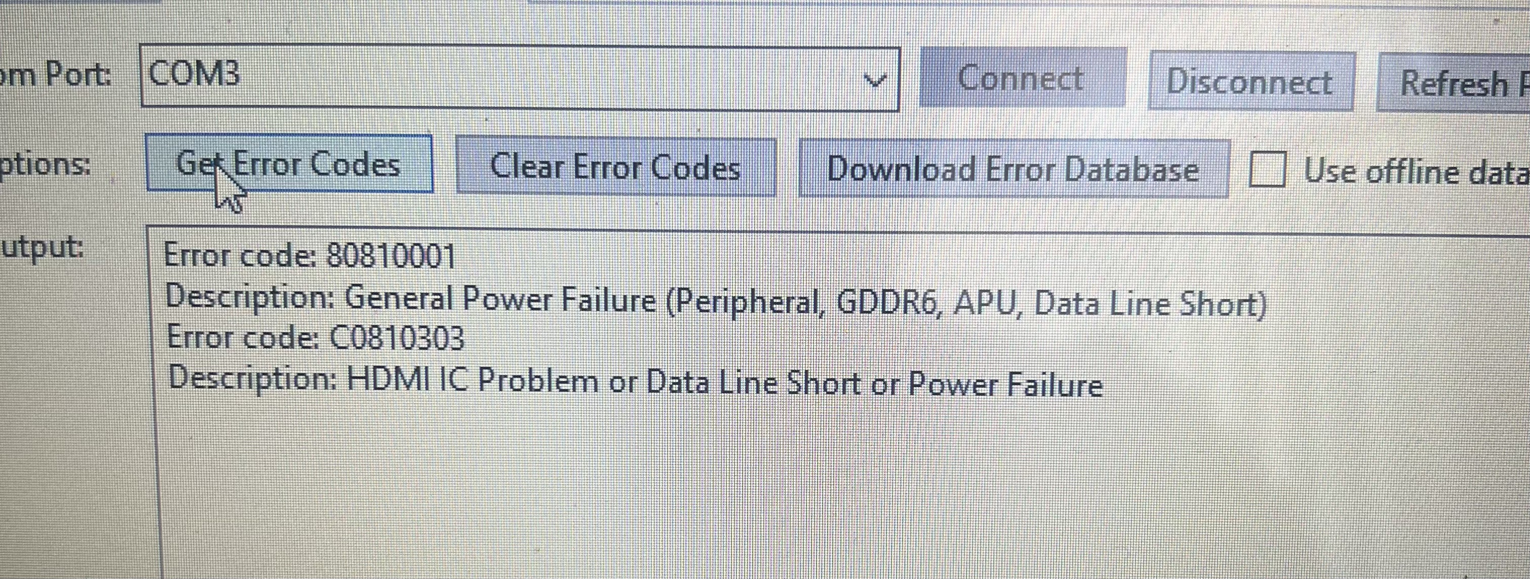
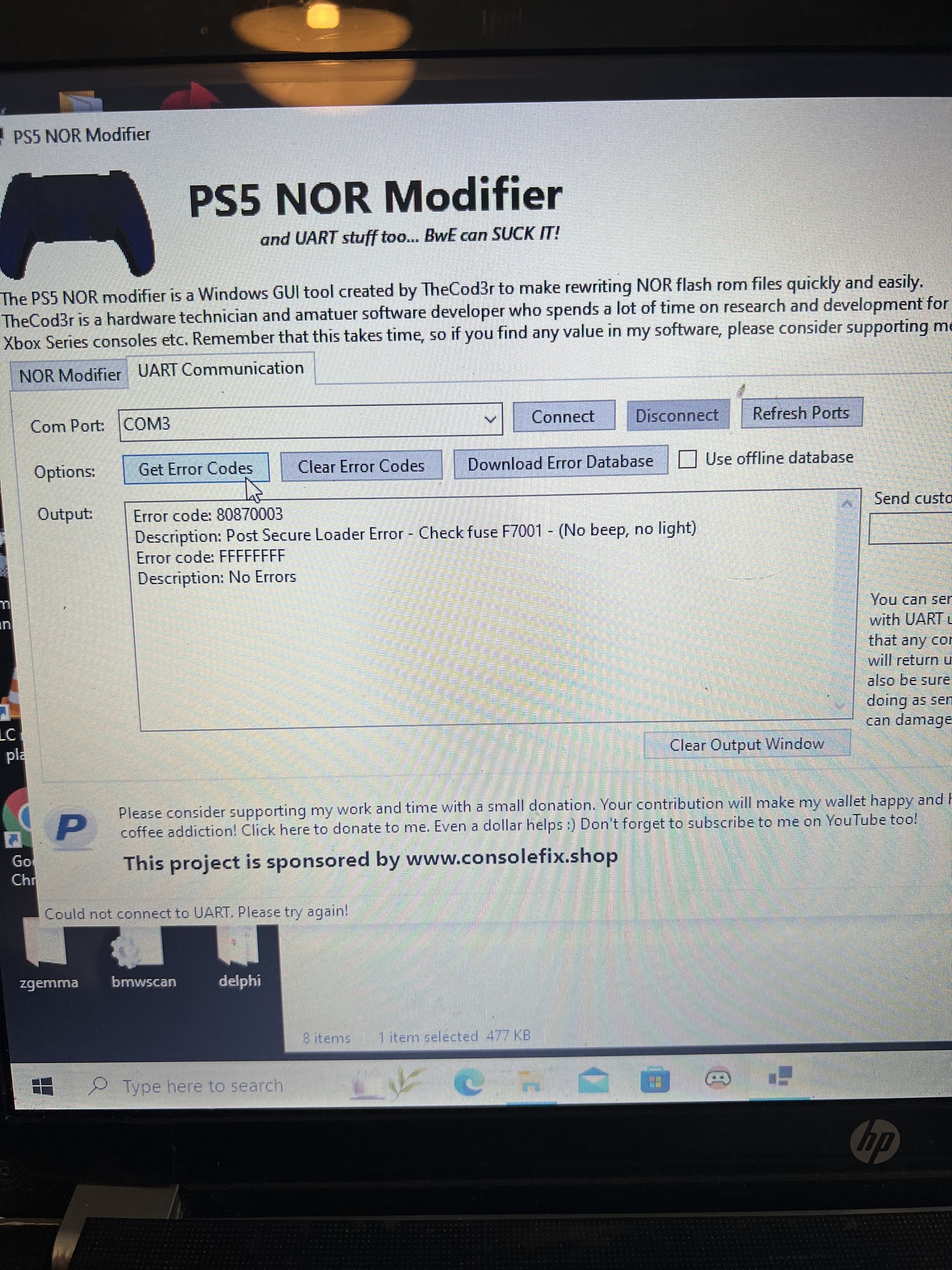
I’ve used the coder gui uart program but I’m having no success with it
It’s either I’m doing it wrong or there’s no com with the board due to southbridge not turning on .

I’m not familiar with using git hub etc I’ll get my head around that and see if I get different results ,

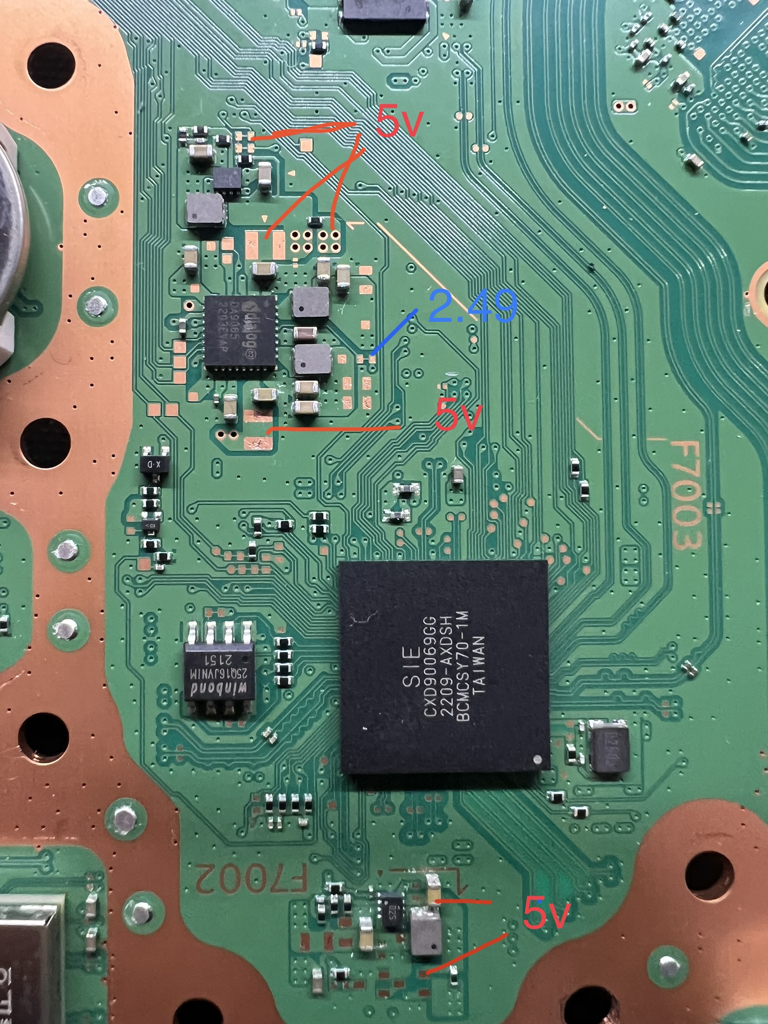
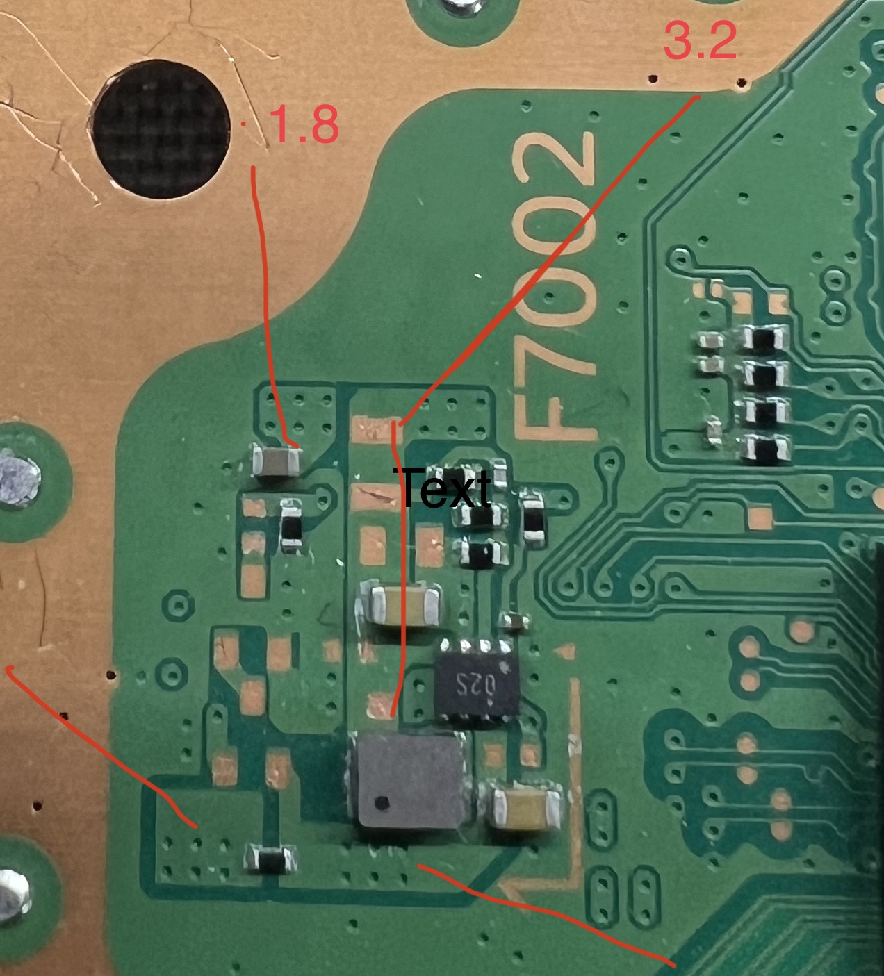
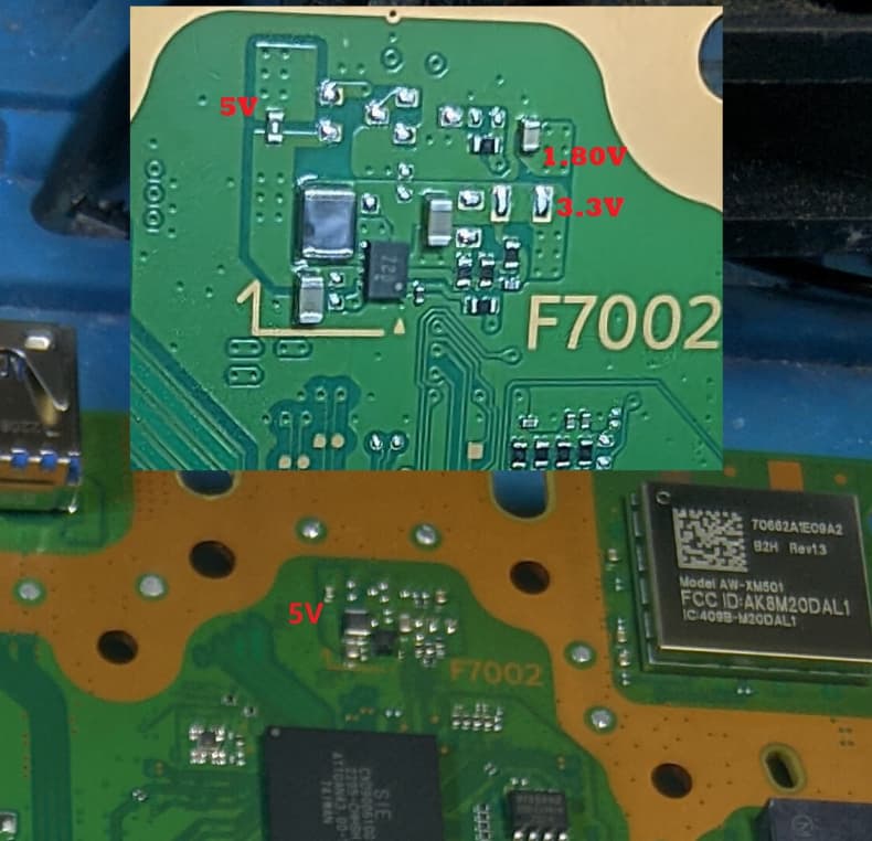
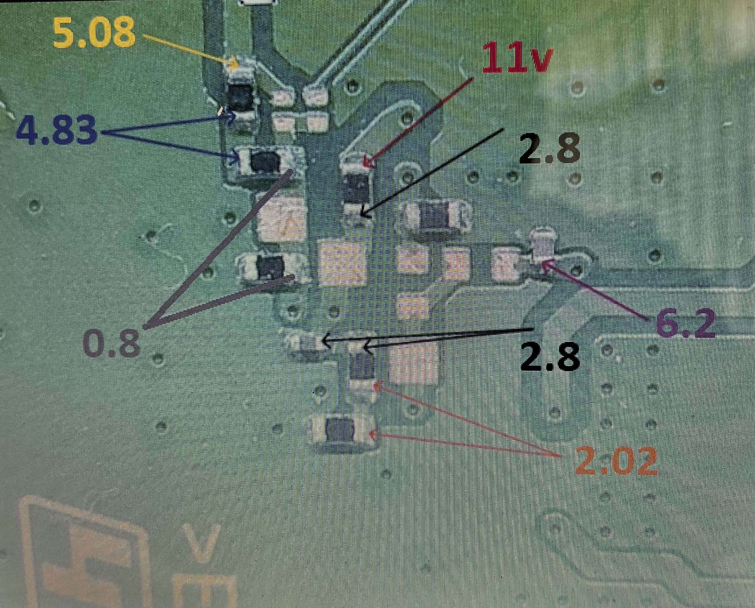
I was hoping to find a map of what voltages should be where

I’ll do some more reading and have a go at using uart again :+1:

I would check if both pads for TX and RX have 3.3V.

The programmer should be set to TTL mode.

If only connect to GND and TX->RX CH341 at inserting the power plug into the PS5 on the terminal program (like PS5 wee tools) there should be an output after 5 - 20 sec:

OK 00000000:3A
$$ [MANU] UART CMD READY:36

No 3v on tx or Rx
Digging around I get these voltage readings
12v connected on the bench not switched on no beeps or lights just powered on the bench

If there is no 3.3V at TX and RX the southbridge is not powered or defect. So no beep and no light.

The pmic should show 3.3V and 1.15V. Are these lines shorted?

No shorts
And no 1.15 or 3.3v at those components

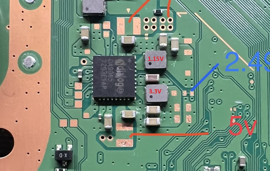
The DA9065 ic should generate the voltages for those lines.
If the 5V input reach the ic and the 3.3V output is missing without a short, I guess the DA9065 is bad.

I’ve ordered a replacement
I’m in the uk and can’t seem to get my hands on anywhere in this country

So Ali express and a bit of wait

I’ll update when I’ve received

Can I ask where you obtained the voltage readings from ??

Is it just a case of over time you know what should be outputting to where ? Or you have notes or a site with the info on ??

I intend to build my own notes from now on thank you for the reply’s it’s very much appreciated :+1:

FixMyApp on youtube is a good start for trouble shooting.
The standby voltages are one of the first things I check on defect PS5s if the system has trouble to boot.

My chips have arrived (bought x2 just incase )

Replaced chip and am now getting the voltages in and around that chip :+1::+1:

Tried to power up and I get x1 beep no other lights or beeps
Tried safe mode but won’t double beep

Connected uart
Am now getting readings (so guessing the south bridge is now at least responding )

Following errors
80810001
C081030

I would check near the fuse F7002 if the voltages for the wifi ic are present.

I’m getting the following
Strange values if the pic you’ve sent is correct ?
You sure the top two voltages are the correct way round ??

I’m getting 5v ok on the right pad and 4.8 on the left pad at the bottom as per your pic (I’m guessing the 4.8 is within tolerances ?)

I have actual no edm-03x board with two power rails for the wifi ic to check.
Maybe @jkyoho has one and can help.

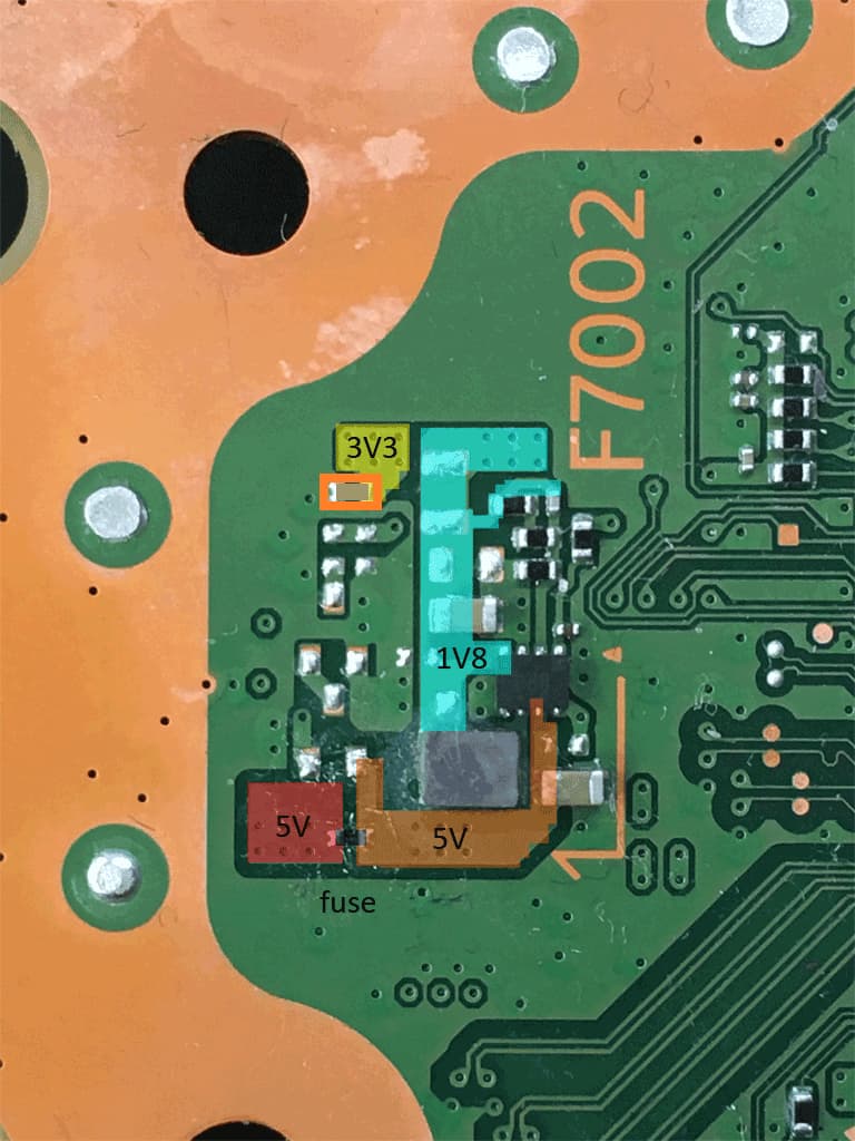
The 4.8V are a bit strange because the fuse shouldn’t effect the voltage. On both side should be 5V. I would check in resistance the value of the fuse.

1 Like

Should be 5v on both side of F7002 fuse, edm-03x f7002 area gens 3.3v standby from F7002 5v standby

2 Likes

So fuse replaced
Unable to check it as it flew off into the forth dimension when I tried to probe it :+1:

I’m now getting 5v both sides and all readings as above .

Ps5 back together to test I’m getting one beep no fan spin and nothing on screen
Unable to boot in safe mode won’t second beep ,

Interesting enough before I put it back together for testing I’m now getting this on uart

sorry unable to edit above post

but fuse at f7001 is fine
power button responds (beeps ) no lights no fan spin etc

Checking in and around f7001 as per uart
I get 5.08v at the alloy cap and on both sides of fuse f7001
And the following readouts just below f7001