I’m working on a PS5 EDM-010 revision board. Never been touch before.
totaly dead, no beep no light
PSU is good
On bench psu, stuck at 0,015A
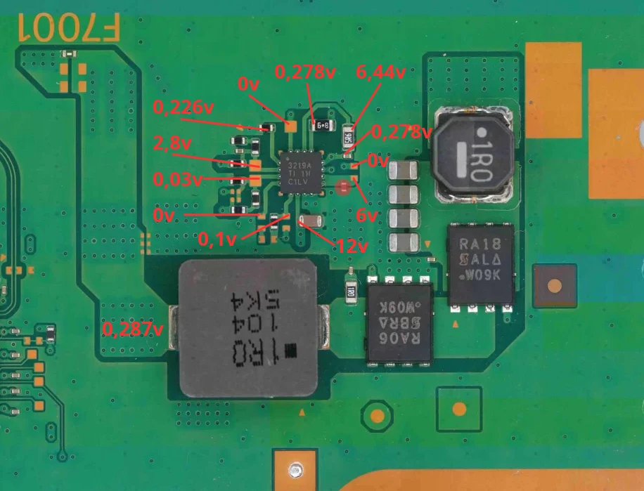
After some research, found a very low resistance (3 ohms) near 3219A component, (pin 9&10 concerned)
I removed the chip, but low resistance was still there. Injecting 2v at 2A show me a full short on the little component (capacitor?) beetwen ground and this line was shorted.
So i removed the component, the very low resistance on the line is now gone.
I resoldered the original 3219A (but not remplacing the small capacitor) and tried to see if 5v is restored, but nope.
Injecting 12v show me nothing on bench psu. Actual voltage are there:
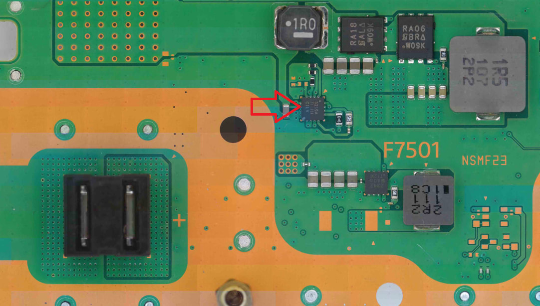
What resistance to ground on f7001? if 5v rail does not have low resistance to ground, try to replace 3219A from F7501 nearby and see if you have 5v back normal
On f7001 i mesure 0,456v in diode mode, more than 3M ohms to ground.
so next step is to replace 3219A, but can i let the circuit without replacing the shorted capacitor? I don’t have another donor board, so if possible i will let the circuit without it.
So i only replaced the 1UF 10V shorted cap from an iphone 5C donor board. Now i’ve got my 5v back ! I suppose 3219A IC is not dead.
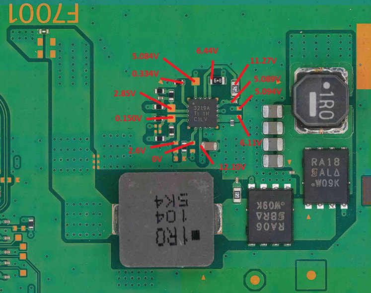
The only difference is a little more voltage on 9&10 pins from 3219A, 6,2v where it was 6 before. Maybe it need more than 6v to enable the chip, and the boost is done by the cap.
To complete, size for this cap is 0201, not 0402
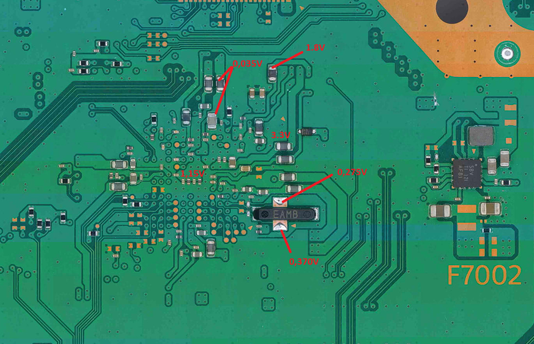
Need to check all rails now, but i’ve already checked 1.8v / 3.3v / 2v and all are presents. That’s a good new.
Unfortunely, my bench psu don’t show any consumption. It’s completly flat, 0.000A curent drop.
If all standby voltages are presents, what to do next?
How to check if NaND BIOS is corrupted? (i’ve already removed and dump BIOS on others boards, but i don’t know how to observe a potentially corrupted bios
I would check the SB pmic (DA9065/RT5126) for correct readings. 0 A usually means that the SB isn’t turning on, which results in no UART communication.
I found something strange. When i mesure the 3219A on pin #3 (VFB - 0,150V), there is an audible clicking around DA9065. Not sure it’s exaclty the chip making that noise, but it’s in this area. It’s not loud, but it appears only when i mesure this pin. Remove my probe stop the sound. Any idea?
Pin 13 (EN2) enables the outputs at pin 7, 8, 18 and it is enabled (PSW_SSB_1) by the southbridge.
Because of the 0 A, I guess the southbridge is not working at all.
To understand the issue more clearly, I’m trying to visualize the boot sequence.
The board receives 12V from the PSU, which is converted to 5V by the 3219A. That 5V enables several ICs that generate the standby rails such as 3.3V, 1.8V and 1.15V.
From my measurements, the Southbridge is receiving those standby voltages, and the BIOS is readable and confirmed good.
I have also checked for shorts around the Southbridge and have not found any shorted rails or suspiciously low resistance readings.
My concern is that I may still be missing one of the rails required for Southbridge startup. If one of those prerequisite rails is missing, the Southbridge could remain inactive and never progress further into the boot sequence.
Is there a list of all rails that must be present before the Southbridge can start executing code and continue the power-up sequence?
I want to make sure every required power rail has been verified before considering a Southbridge replacement.