hi
I have an EDM-031 board with no USB ports—neither on the front nor the back. In the photo, you can see three components: two 8-pin ones, plus R1833 and R3334. I had to replace two components—the 3219A and R1833—because they were dead. Even after that, there was still no USB functionality. So, I checked R3334 and realized I wasn’t getting any diode reading on pin 5, so I replaced it. It’s fine now, but the console won’t work: the blue LED lights up for a second, and I get UART codes C00C0303, C00C0303, and 8081001. I’d like to know the diode and ohm values for all the pins, if possible, so I can figure out which component is faulty. Thanks in advance.
Which photo? 
Where is the reference to R1833 and R3334?
C00C0303 is normally pointing towards an issue with the communication with the VRM controller (XDPE chip).
Hello,
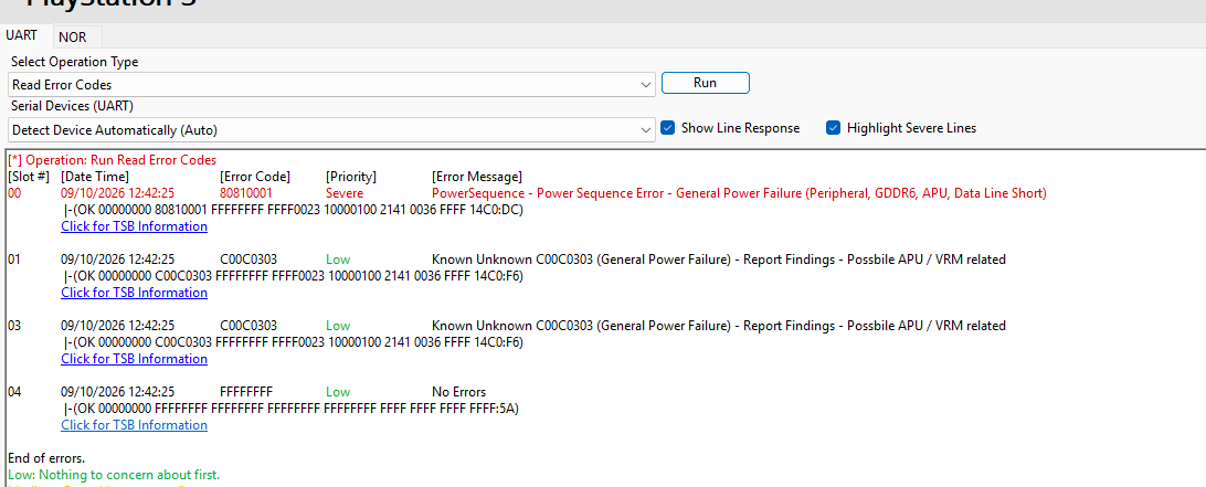
I have an EDM-031 board with no USB port—neither on the front nor the back. In the photo, you can see three components: two 8-pin ones (R1833 and R3334) and the 3219A. I had to replace two components—the 3219A and R1833—because they were faulty. Despite this, the USB connection still wasn’t working. I then checked R3334 and found no diode reading on pin 5, so I replaced it. I now get a diode reading—which I believe is normal at 0.5V—but the console won’t start: the blue LED lights up for a second, and I get UART error codes C00C0303, C00C0303, and 8081001. If possible, I would like to know the diode and resistor values for each pin to determine which component is faulty. Thanks in advance.
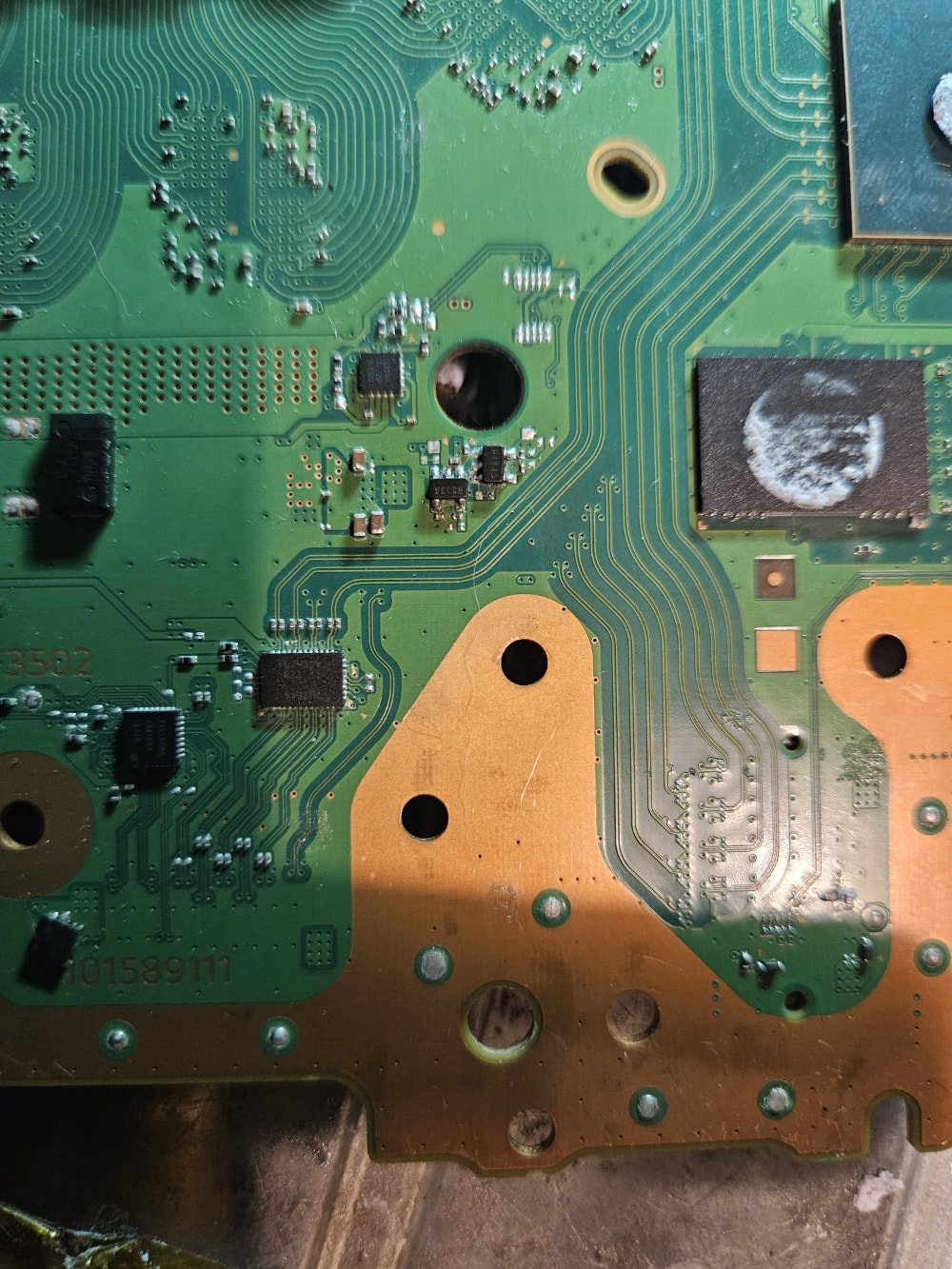
Sorry, the translator isn’t great. Why is this error appearing? To me, the issue stems from that line on pin 5, which gets inhibited when the component is faulty.
Pin 5 at the both 5 legged pmics (marking ‘R3334’ = TLV75533, marking ‘R1833’ = TLV75518) are the output pins. If I’m right, the outputs should be the lines: 1.8V_SOC_V18_S5 (0.59 V diode) and 3.3V_SOC_V33_S5 (0.49 V diode)
It is a bit all over the place:
You wrote about USB ports not working,
replaced pmic chips at APU lines and
posted UART errors pointing to issues with the XDPE chip
Yes, it’s baffling. If I have an R3334 chip with a non-functional output—showing nothing in diode mode—the console powers on but has no USB ports. However, if that same chip is working (showing 0.59V in diode mode), the console displays a blue LED and the UART code mentioned above. What is the connection?
Does the 1.8V_SOC_V18_S5 line go to the XPDE?
I traced the 1.8V_SOC_V18_S5 line on an EDM-010 schematic and found that it connects to two small capacitors on the back of the CPU; these lead to a small component, Q3602, and finally to IC3602. The console won’t boot even with a “good” R3334 installed. I removed Q3602, but it still won’t start; since the only component between pin 5 of R3334 and Q3602 is the CPU, should I conclude that the CPU is dead?
Does pin 3 at ‘R3334’ have 3.3V or is the output line at pin 5 shorted?
If not, the southbridge isn’t enableing the pmics due to a detected fault.
It is possible that this lines are not turned on, because XDPE does not report ‘I’m ready’ back to the southbridge.
The USB ports data lines are all controlled by APU. The power of the USB ports on the back can be activated/deactivted by southbridge.
Please post the whole UART error string.
If my R3334 is good—yes, I get 3.3V on pin 3 (albeit briefly) and no short circuit on pin 5. However, if I install an R3334—with no diode reading on pin 5—I only get 0.5V on pin 3 and nothing on pin 5, and consequently, my console works normally.
3.3V at pin 3 = southbridge is sending 3.3V to enable the output.
Can you lift the chip so that the both pins on the output side are not touching the mainboard and check if 3.3V are present at the output at pin 5?
j’attendais cette question;) si je soulève les 2 pattes 4 et 5 j’ai une tension de 3.9v console souus tension. si j’essai dde la démarer, led bleu 1sec. cette ois les codes ne sont pas les mêmes, voir photo
Uploading: Capture d’écran 2026-10-09 145503.png…
la poto à du mal à charger voici les codes 80810001 et c00c0002
The photo is having trouble loading; here are the codes. 80810001; c00c0002
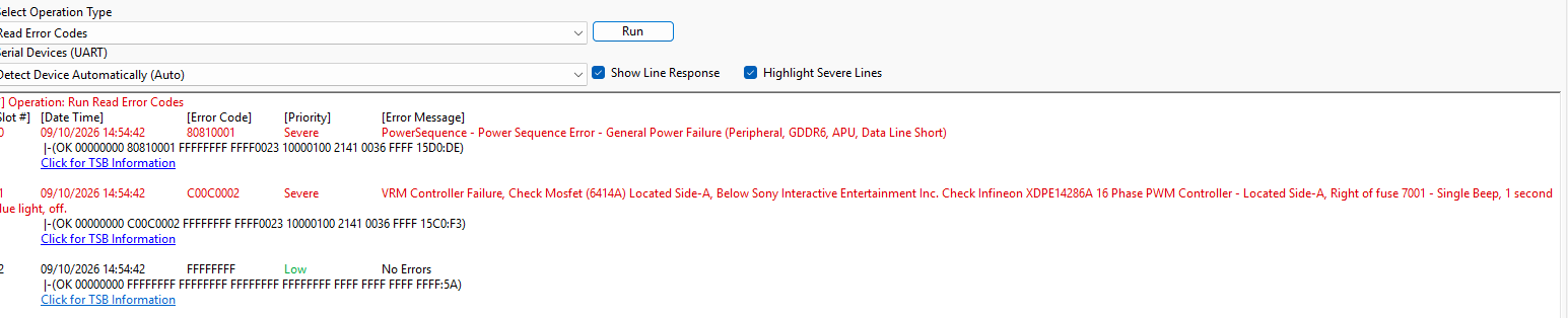
3.9V are a bit off from 3.3V which should be the output.
Trying to start the PS5 with missing parts or not propper soldered parts makes no sense.
Usually the southbridge makes a pre boot test when the power cord is plugged in. If any issues appear during this test the southbridge will write UART error codes and stops in the sequence step where the issue shows up.
Thanks for the comment. I realized that component 041 was missing. I ran the test again, and this time I have 3.3V on pin 3 and 1.8V on pin 5. I’m not sure if this is normal, but I’m getting readings of 52 ohms on pin 3 and 15 ohms on pin 5. Is that normal?
You wrote that you had 0.59 V on pin 5 in diode mode. Sure you reading is not 15 k Ohm?
Yes, in diode mode I get voltage readings, and in continuity mode, ohms. I just re-checked the measurements: 0.620V in diode mode (red probe to ground) and 26 kΩ in resistance mode, though the reading isn’t very stable—it tends to drift upwards.
Sorry, for me it is hard to follow.
The pmic (marking ‘R3334’ = TLV75533) is soldered back down to the board and you have the right voltages and a propper k Ohm reading. If so, this one issue should be solved.
What is the component 041? Do you mean a transistor with marking ‘41’ (DTC044EUB)?
What is the story of this mainboard?