I got a PS5 edm-031 already disasembled with the note that the southbridge should be reballed.
First thing I fixed was 0.3V on the 5v rail. A cap was not propper soldered and therefore TI3219A was not delivereing the right voltage to the high side mosfet which generates 5V.
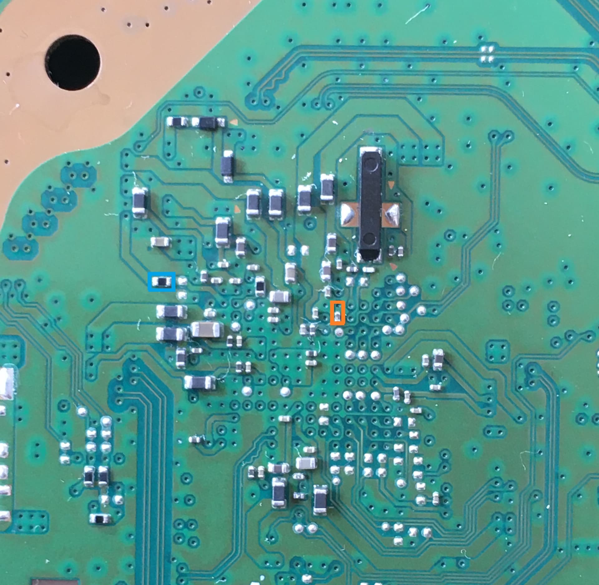
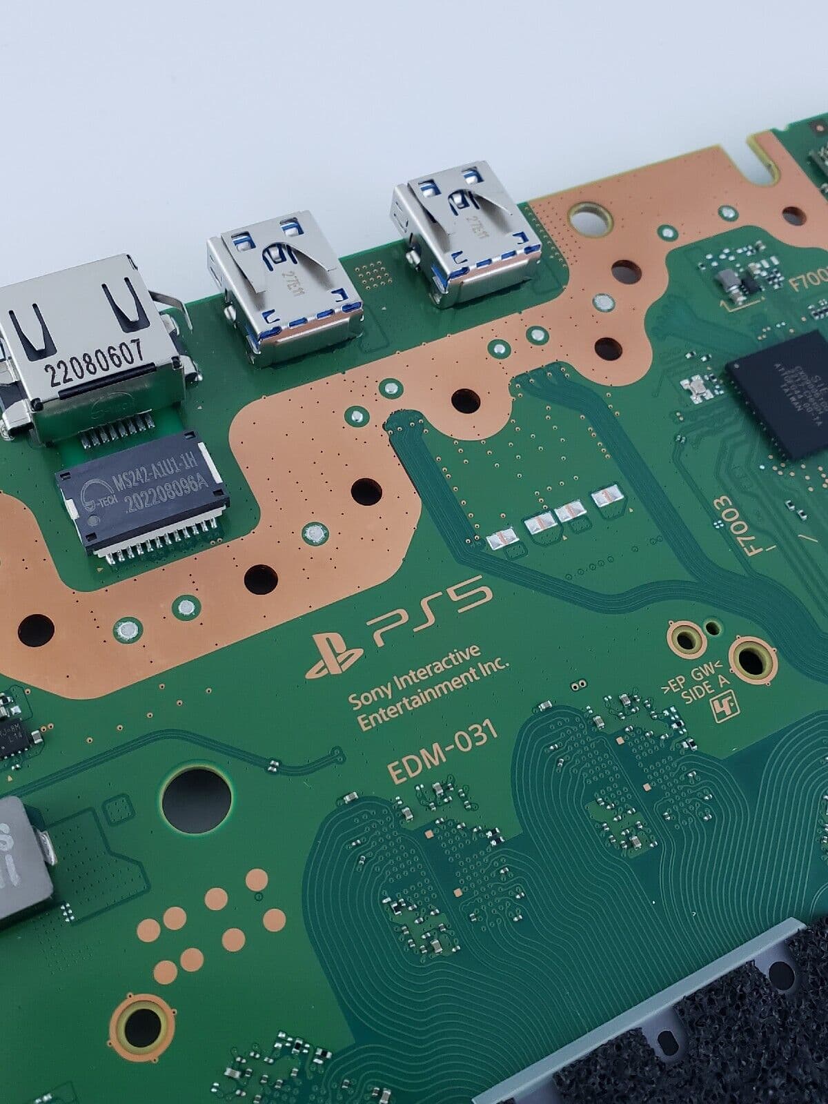
At DA9065 3.3V was shorted. I found a shorted cap on the backside of the southbridge (orange marking). I replaced this cap and the short was gone.
After replacing the southbridge with a known working one and apply voltage, the short on the 3.3V line was back again.
Now I’m on a search for the cause of the reappeard short. And I’m wondering if someone can tell me the resistance of the resistor (blue marking) at the 3.3V line?
You’ll have to excuse my ignorance as I’ve done very little on PS5.
Is the assumption that the Southbridge is now responsible for this short on the rail? Have you removed it just to make sure? (or measure resistance to ground at a few of the rails locations to see which represents the lowest value)
Do you have an osciliscope? As if the southbridge has been fried and if it’s pulling the 3.3V rail low, then I’d want to check this rail with the southbridge removed and see if you can capture any spiking voltages above the producers max rate (I guess DA9065 is responsible for generating this rail?) . Now, I don’t know the power sequence / order, so perhaps without southbridge installed the rail won’t come up (?) In which case, I’d provide it’s input manually and/or it’s enable (if possible, not checked) . If you do have a scope, I’d also take the oppurtunity to check the 5V rail too. (if that is indeed the input)
I’m guessing you’ve already swapped out the DA9065 IC? (again I’m guessing this is the producer) as I suppose it’s possible the IC was damaged or partially damaged when the cap was shorted, rail was pulled low as a result likely preventing it’s total failure, short was cleared, voltage goes high and total failure resumes (could also be two fold if that 5V rail you mentioned was the input voltage?)… Or the opposite, IC failed, took out the cap just pior to it’s total failure… All guesses mind you
Also, thinking about it. You had one cap which wasn’t properly soldered / broken joint (?) and another which was bad. So I guess this was an impact damage situation (?) so maybe you just got really unlucky and there was another cap which just so happened to be on this rail too which was on the verge of failure (or it’s bad connection and power on caused it’s failure) Though, that’s some odds, that would be 3 cap failures then, all on the same rail which would be super unlucky / rare.
Also, maybe just trick of the light, but this looks a little odd but maybe normal or just a bit of fluff
If the southbridge is on the board the 3.3v rail is shorted. After lited the sb again the short is gone.
The DA9065 is the power supply for the sb and I have changed it already. Without the sb all voltages are present (5.1v (in), 5.1v (out), 3.3v, 1.2v)
Sometimes a osci would be handy. But till now I don’t have one. Next thing on the nice-to-have list.
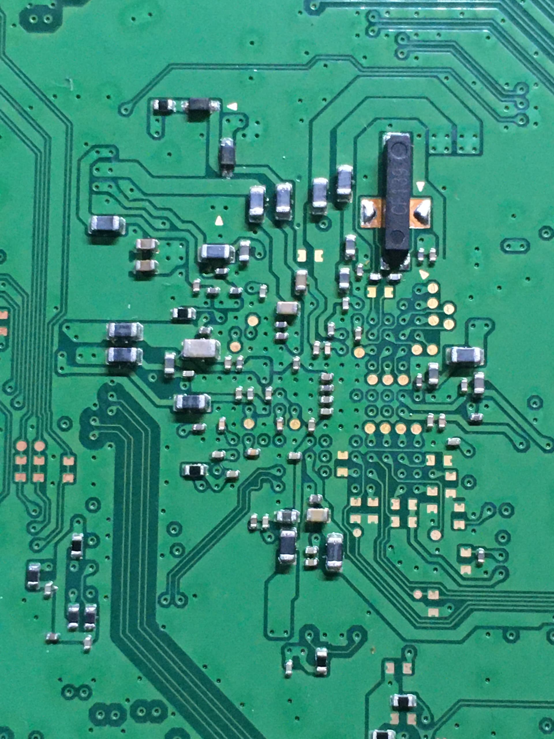
My guess is that the sb isn`t shorted and have one shorted or bad input which open internal 3.3v to ground. On the thermal cam it is visible that the part of the 3.3v where the blue mark resistor is, the 3.3v line is getting hot. The resistor reads 1 ohm and I have no other edm-031 with similar design. At a edm-010 and edm-020 this line is not there in this form.
Yeah it’s one of those things that gets use only once in a blue moon my end. In my case pretty much soley used in situations like this… I sometimes think I wasted money on it with it sitting there collecting dust . I think you have the UT61E meter too? you have that “peak” mode on it, which is supposedly similar to a min/max mode (but showing peak voltage instead instead of average) but I’ve never had good luck with this mode… never seems to work or work how I expect… maybe it’s not intended for DC voltage or I’m an idiot and am not using it correctly, but maybe it’s worth a shot your end monitoring the input and output of the IC.
Maybe a LA could pick up on this sort of thing too, would be cheaper than a scope I suppose.
It’s possible I suppose, though it does seem to me that the SB IC has kicked the bucket in this case and my best guess would be due to eratic voltage on the two rails at play, maybe the first time the capacitor failed first (due to overvoltage) and “saved” the IC first time round. Though I could be wrong.
I see, hopefully someone else can confirm. @jkyoho is usually the man on this front
What I’d say is, and I unfortunately can’t look into this for you, but failures in this manner (assuming overvoltage) are usually mosfet related / intermittent fets… usually paired mosfets, and one being partially bad.
I guess to check the SB IC, you can check the IC out of circuit and see if the 3.3V corresponding line resistance to ground is, if it’s shorted out of circuit you can say for sure the IC is bad.
I should also add, mosfet control IC’s would also be applicable in some cases too (if that applies in this case I don’t know)
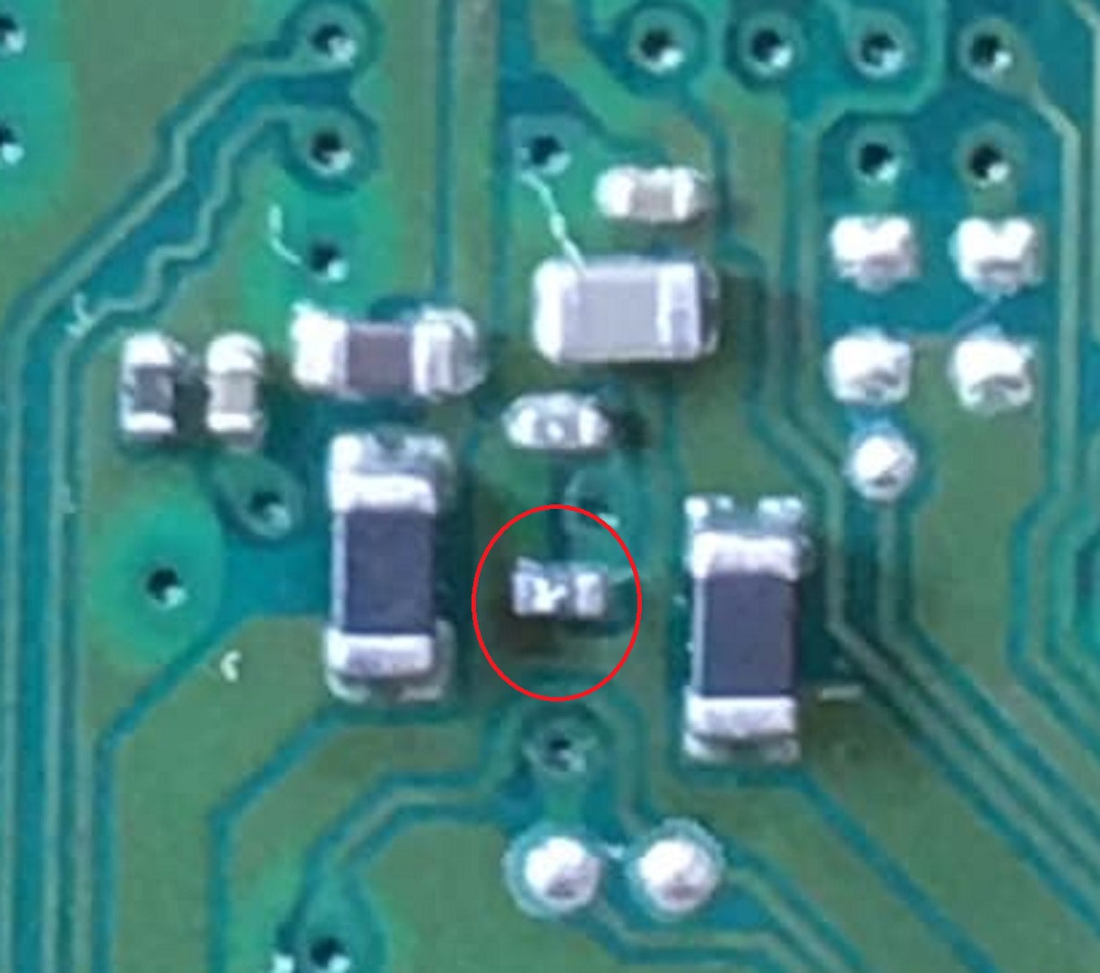
Maybe it’s a current sense resistor or just a zero ohm link resistor and they opted to scrap it on alt revisions and just use continuous trace. Kindof looks about right for it’s size… guess it offers further confirmation to this, if the same line is just a trace on other revs too
At an edm-020 at the similar spot (but I don’t know if it is the same line) I have a resistor to ground and a reading of 24 kOhm on the line, which is different to the 6.8 kOhm readings of the 3.3v line.
You see the two testpads on the diagonal next to it, count the VIAs to the left (even though some vias look different) and it’s the same third one over it seems like. Also looks like the arangement of all the testpads on the right side are the exact same between variants… so maybe the line comes out on one of these too
Though I’m probably wrong. Sorry, bit hard to check this stuff without a board my end.
Just double checking. This is the resistance when measured across the resistor right? (just checking this isn’t / wasn’t relative to ground when the SB IC was still on the board).
Side question. What are those two diodes doing / where are the going ?
Also, did you verify the SB IC out of circuit and check it for the short on the 3.3V line/pin to ground?
The 24 kohm line appears at edm-031 three resistors left from the blue marked resistor.
I checked the desoldered sb and there are no shorts between the power rails and different gnds on the pins of the ic.
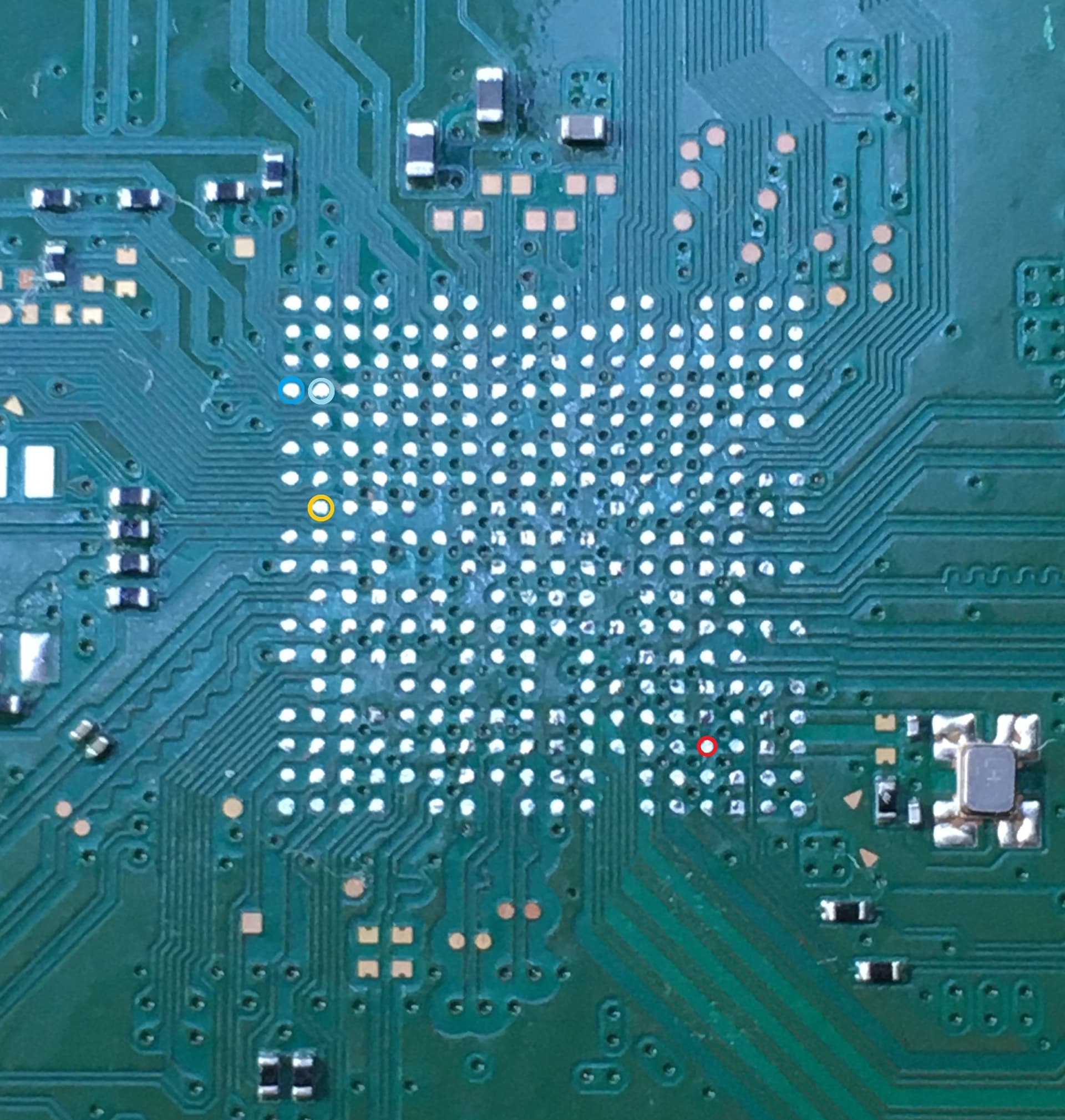
Now the funny thing shows up: I removed the resistor, checked the line for resistance (oL, so I guess I isolated the line towards the sb) and soldered a little wire. I found the matching pad on the other side. (red marking)
I went over to my edm-020 board and looked for the same pad. This pad is a direct gnd pad.
At gbatemp I think I got the answers, why this 3V3 line is shorted and this bga pad at a edm-020 is a direct ground:
The southbridge is not the right version. Instead of CXD90061GG it should be a newer revision CXD90069GG.
I never thought about that another southbridge revision could be the problem.
at desoldering the sb, I noticed the quick desoldering and the shiny solder balls. Indicates leaded solder and that the sb was changed or reballed.
the shorted 3V3 line and the discovery that on the backside of the sb the similar ‘shorted’ pad is a ground pad at 61GG sbs. So something doesn’t fit for a 61GG.
the replacement and the sb which came with the board are working fine on an edm-020.
At gbatemp user testerfan give me the hint, that my layout where the resistor is placed, is for a 69GG and not for a 61GG. He also mentioned that the nor contains information anbout the sb, so even if I edit the circuits so that the 61GG is hardware sided correct implemented, infos on the nor must be altered to make a 61GG working instead.
Update:
I found someone who could give me a dump from an edm-031 with 61GG southbridge. I put the dump on the nor and voilá: the PS5 is starting again.
Now I’m trying to find the differences, so I can move the original disc drive informations or the specific 61GG informations to the nor, so I could use the disc drive.