Sorry, I got things mixed up!
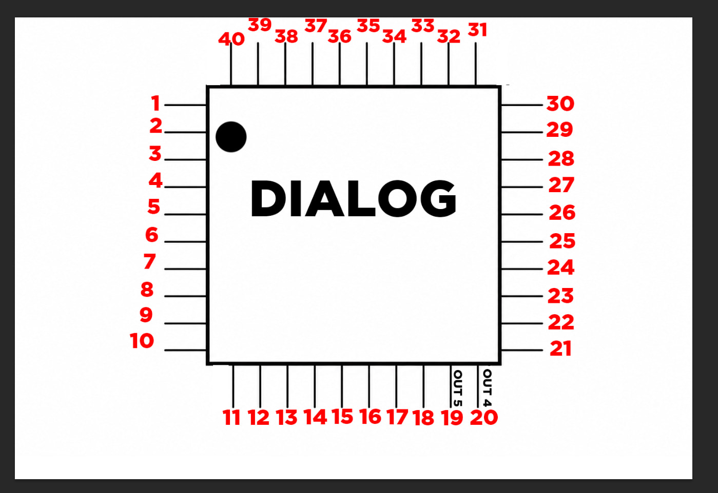
I’ve renumbered the pins, using the dot in the top-left corner as a guide. Are they numbered correctly now?
No. 
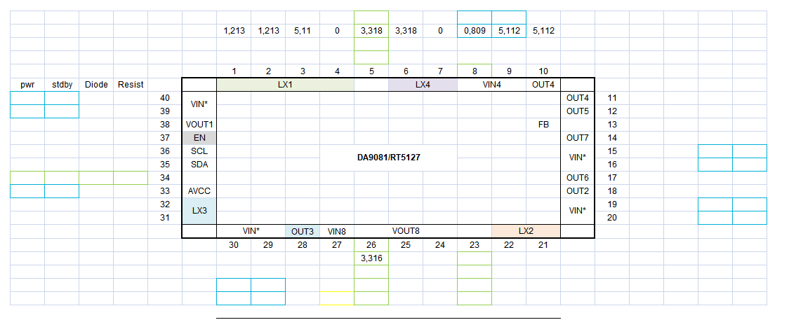
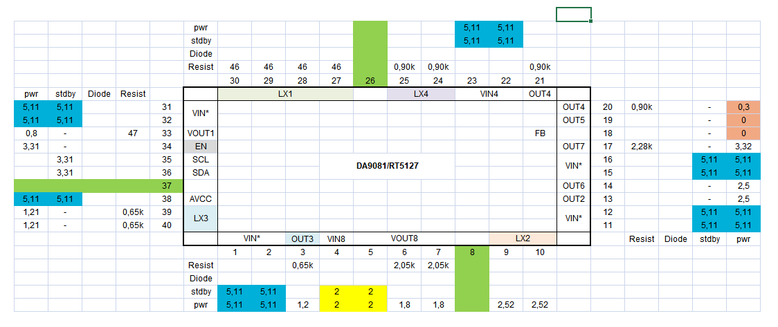
In general the pin numbering at qfn chips is counter clockwise.
If you change the numbers in the table the pin names don’t match anymore.
In this orientation the chip matches the table:
If you measure resistance and diode mode, unplug the power from the console.
resistance: black on ground, red on pad
diode mode: red on ground, black on pad
At the SSD pmic you have aprox three seconds to measure the voltage, after the time if not fully started, the EN is disabled and you need to press the start button again for the next voltage measurement.
Thanks a lot, and please forgive the “noob” in me, hahaha…
I’ll take the measurements and update the table with the data I get.
One question: I’ve noticed, for instance, that 5V can always be measured on the VIN pin—does this mean the PMIC has fully powered on and remains active?
Also, I wanted to give you an update regarding the UART errors. After the PS5 actually emitted its beep, I connected the UART, and there’s a new error code in addition to the one I’d already found.
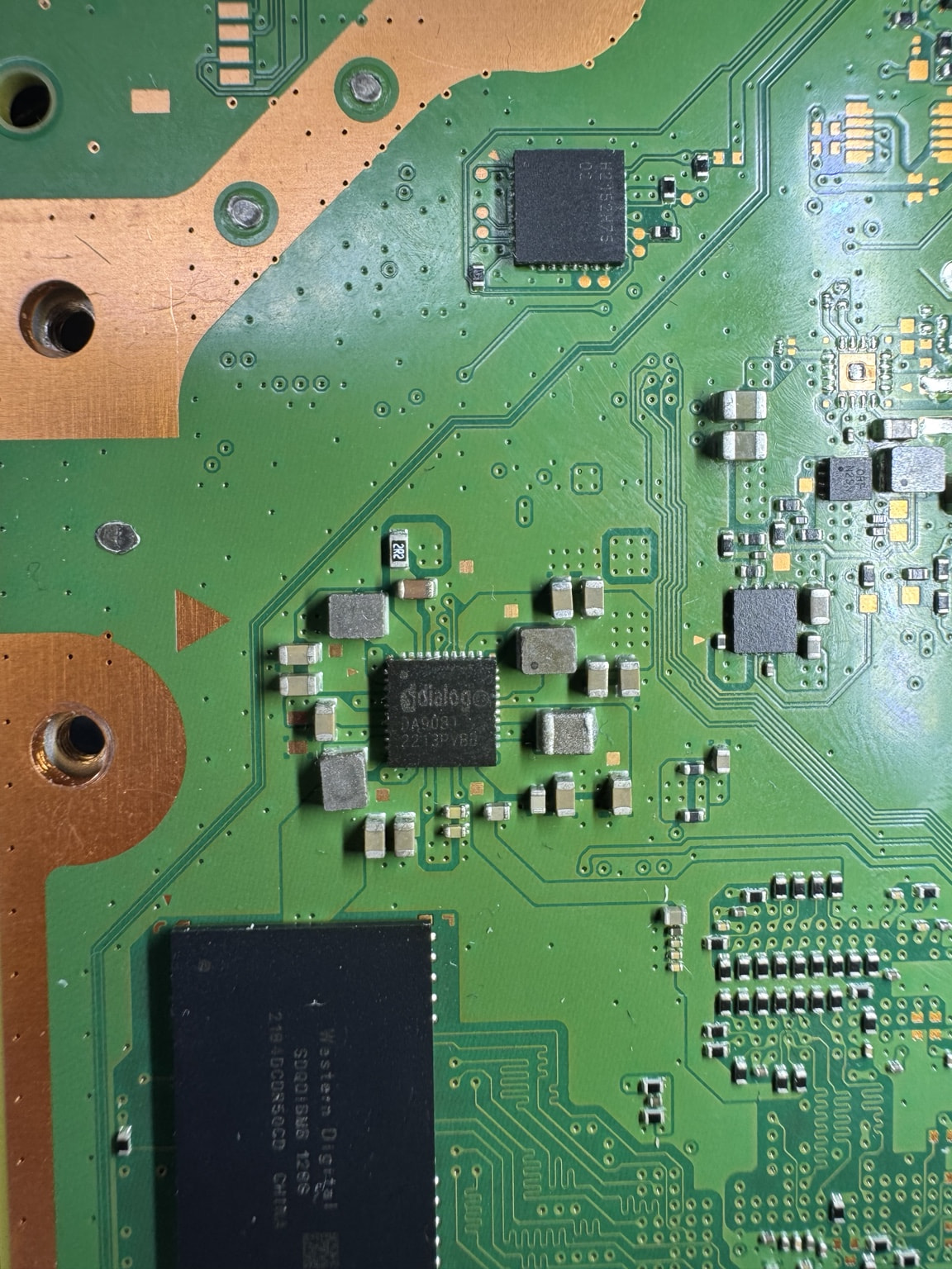
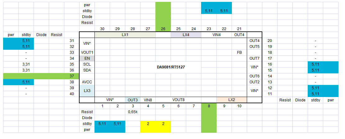
Another thing: I’ve now determined the correct orientation of the chip for taking measurements. I tested pins 1 through 10, and the standby voltage readings look correct.
I’m attempting to measure resistance (with the power disconnected)—placing the black probe on GND and the red probe on the individual pins—but I only get a stable reading on pin 3 (0.65kΩ). For the other pins, the value keeps rising as long as I hold the red probe against them.
Is this behavior normal? Should I wait for the resistance reading to stabilize?
The 5V input is the 5V_EVER line, so it is always present. The southbridge enables at start botton press the SSD pmic at pin 34 and the outputs should show their voltages.
If an error occur, like the UART errors show, the southbridge is disabling the SSD pmic.
The UART error codes are all pointing to an issue with the SSD controller. This could be the SSD pmic, the SSD controller or a cap on the SSD powerrails
At resistance measurements it could take a bit to have a steady reading. But in the end I guess we are looking for a short or massiv other value.
If you have 0.65k Ohm it is ok. If you read aprox the same M Ohm, k Ohm, Ohm range it is mostly fine.
At the moment I would check if a short is present at one of the outputs.
First issue identified: in standby mode, all pins show the exact voltage specified in the table you provided, with the exception of pins 35 and 36—which should have no voltage, yet show 3.31V.
Regarding the resistance measurements—for pin 1, for example—the reading starts at 6.00 kΩ and gradually climbs to 28.54 kΩ, taking at least 30–40 seconds to reach that value.
I will continue with the diode and resistance measurements. Given the limited time available, I will perform the power-related (PWR) measurements tomorrow, with my brother’s help to toggle the power outlet on and off.
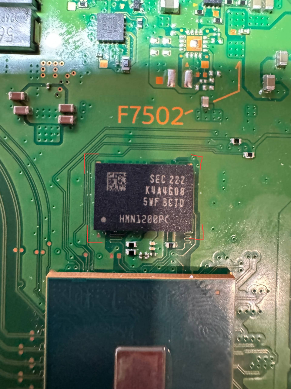
Unfortunately, while taking the PWR measurements, I believe I accidentally shorted some of the chip’s pins. Upon checking, I found that fuse F7502 no longer has continuity, so I will need to order a replacement; it will take a few days for the part to arrive. I hope you will still be able to assist me once I have replaced the blown fuse.
In the meantime, I have attached the latest measurements I took—three sides of the PWR section were measured, with one side still pending. I hope these readings provide some further insight into the issue with the PS5.
The two voltage values that differ from the ones you provided are marked in red.
Also, to avoid any mistakes, could you tell me the specifications for this fuse?
I found these fuses that appear to be compatible on Amazon.
ECSiNG 10-Pack 0402 SMD Fuse 5A 32V Compatible with PlayStation 5 for Motherboard PCB Repair 0402 5 A 32 V Links
A 0402 5A 32V fuse will work. 
So far, the 1.2 V at out4 and 0.6 V at out5 are missing.
What is the resistance to ground at out5?
I measured the resistance at pin OUT5; I haven’t replaced the fuse yet, so I’m not sure if the reading is still reliable given that the fuse is blown.
OUT5 = approximately 60 ohms
60 Ohm at OUT5 seems a bit low.
What’s about OUT4?
I have drawn this diagram to show how I have numbered the pins.
I have re-measured the resistance (black probe to GND, red probe to the pin):
PIN 19 (OUT5): 1.03 K
PIN 20 (OUT4): 0.2 ohm
I have removed the board from the chassis to avoid any ground contact; the power is disconnected, and the UART is not soldered to the board’s pins. For the time being, I have also removed the bridge—which ran from the fan to the 12V pin of the AC IN DET—to prevent any accidental damage to the circuit trace while measuring resistance.
If OUT4 is close to 0 Ohm resistance, this could be the cause why the PS5 isn’t booting.
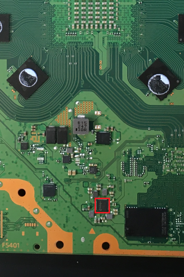
This line is 1.2V_FC_VDDQMIO and powers the DDR4 RAM chip near the SSD controller and the APU.
I would inject 1V 3A and see what is getting hot.
So, should I inject 1V 3A into the OUT14 pin using a bench power supply and then use a thermal camera to see which areas heat up?
Can I perform this test without the F7502 fuse reinstalled?
The fuse is not needed for injecting.
Thanks again. I’ll give it a try shortly and let you know what happens.
In any case, I can tell you that there is another pin with a resistance close to zero: pin OUT6.
OUT6 is the second powerrail (2.5V_DDR4_VPP) to the DDR4 RAM chip. I guess the issue is the DDR4 chip.