Although they told me the console hadn’t been opened and the warranty seal was indeed there, I detected flux residue near bank 3 under a microscope.
I checked the standby voltages, and they’re OK.
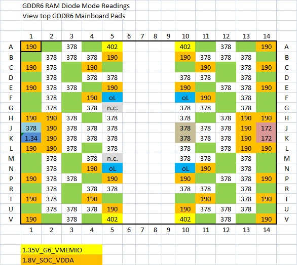
The RAM tries to rise to 1.35V as expected in the test area.
However, I noticed that on the upper test pads of each RAM bank, the voltage tries to rise and then collapses, except on bank 3: nothing is detected, 0V.
Thermal camera test: all 8 are heating up as expected… but I don’t understand why there’s no voltage on the test pad.
Thanks Calvin, you’re always available to help!
If the chip is missing readings, can we assume it’s a defect? If the PCB is missing readings, can we assume it’s an APU?
I tried keeping the chip flat, but it didn’t make any difference.
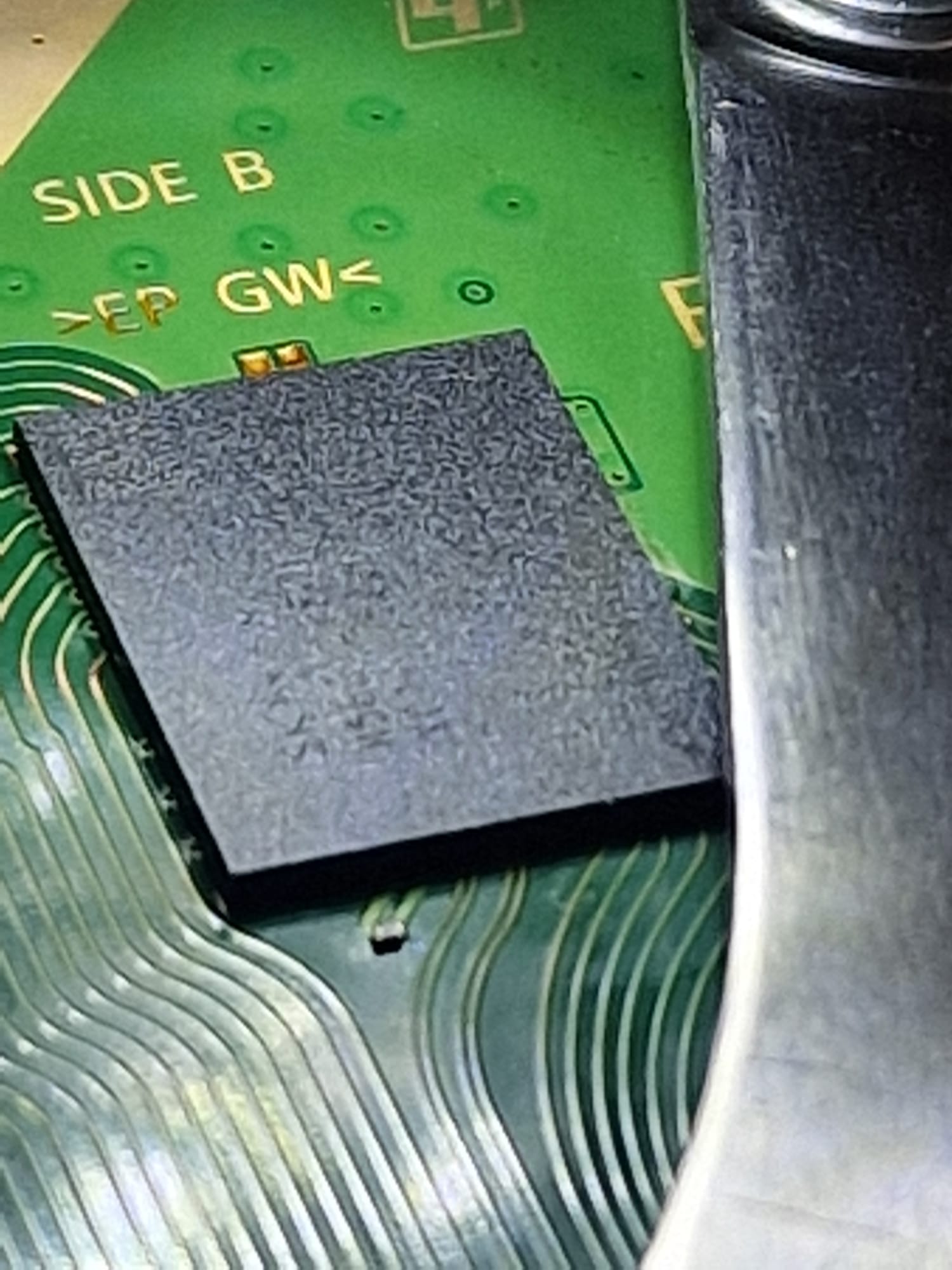
I noticed a slightly thicker and shinier BGA ball underneath… you can see it even without a microscope.
I guess the RAM chip No 3 was changed before, as the shiny leaded solder balls and the flux residue under the RAM chip in question would explain.
Instead of resoldering a RAM chip a second or a third time, I usually meassure the pads on the mainboard at least to ensure that there is no short or o.L. where it shouldn’t be. If a BGA contact is loose at the APU it could end up in the same error code.
I usually go with 450°C and 30% airflow. But I’m not sure if it is compareable.
With the presumably leaded solder balls under the RAM chip, it should be not long heating time.
I replaced bank 3, now it gives me 80801F12…
On the opposite side of the board, the two test pads give me zero ohms… incorrect soldering? Some spheres aren’t touching? Bad IC ? The other test pads of the other ram give over 1kOhms
before soldering the new IC I measured the values on the PCB and they were all present although different from yours (Hynix RAM)
@Calvin I reflowed the RAM…now UART 8081001 and I no longer have 1.35V on the RAM. The resistance ohm on the test pads are back to normal. What could have happened? Before, there was 1.35V coming in…now zero. Bad RAM ? Bridges below? Anything else?
@Calvin I reflowed the RAM…now UART 8081001 and I no longer have 1.35V on the RAM. The resistance ohm on the test pads are back to normal. What could have happened? Before, there was 1.35V coming in…now zero. Bad RAM ? Bridges below? Anything else?
I had to remove the IC RAM again. Looking under the microscope, I noticed a bridge not on the PCB… but on the IC! Incredible.
Maybe it was raballed badly, so I bought it that way.
Once removed, it returned to 80801F12 (without the IC) and 1.35V RAM.
Now I have to reball again and figure out how to set it up correctly
I don’t understand why I don’t have problems with SB soldering while I do with RAM!
One issue with soldering the RAM chips maybe their place on the mainboard, which is designed to spread heat quickly.
I would reball and resolder the RAM chip. For testing I would press down one of the eight RAM chips, while trying to start the system. This for all eight RAM chips step by step. And see if the behaviour on start changes.
Partially solved. There was a damaged pad under the RAM, I fixed it, put the RAM back in and now it reboots. But after 2-3 minutes it crashes. Maybe this IC is damaged or there’s another RAM IC to be fixed