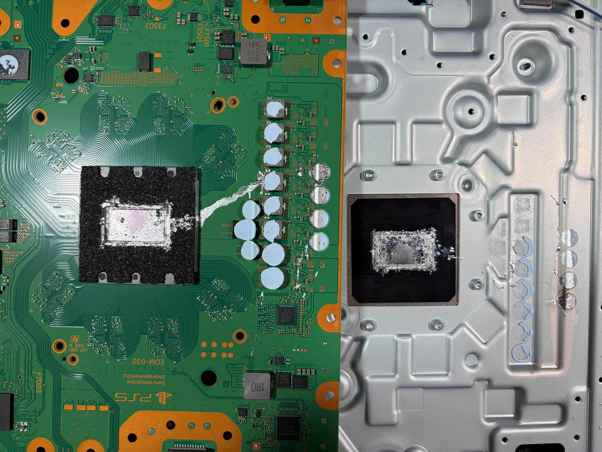
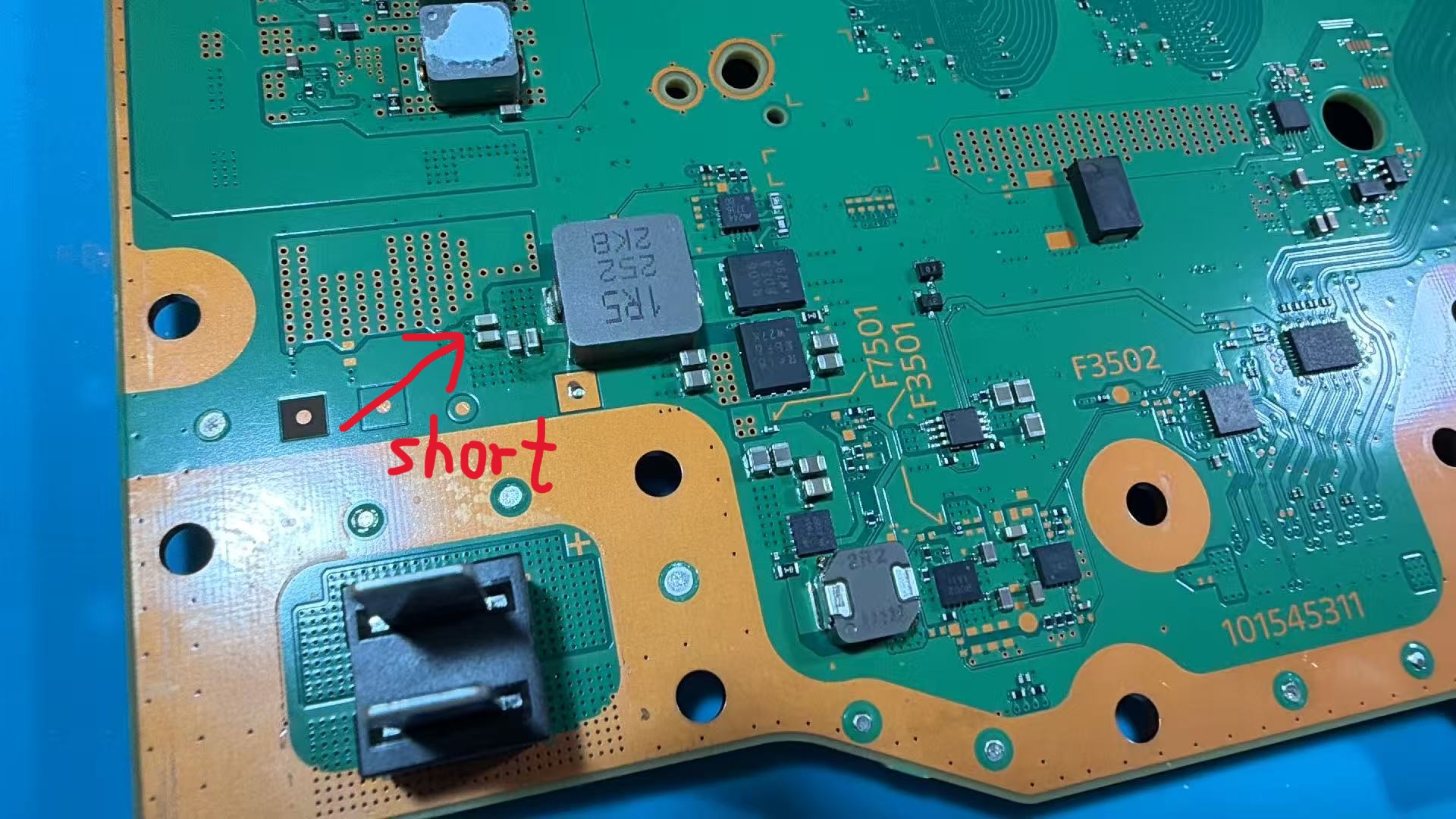
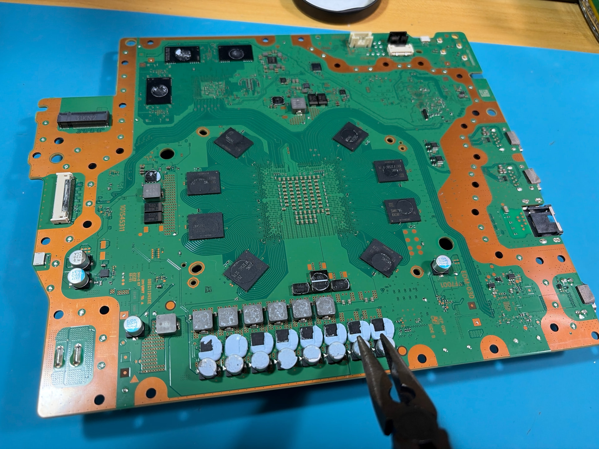
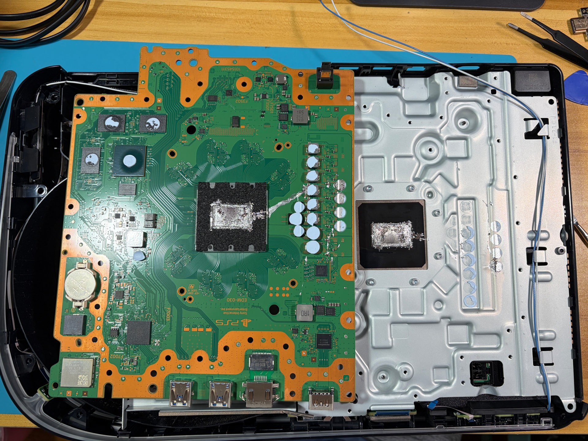
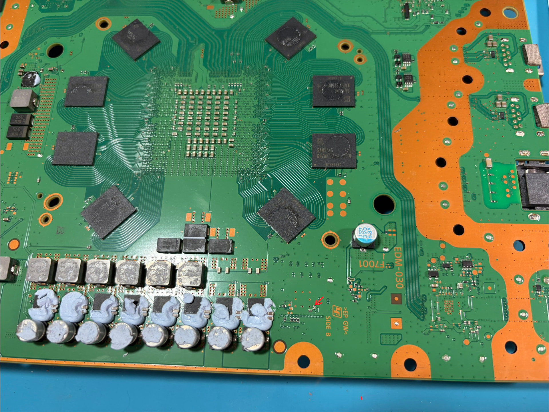
Liguid metal spilled to near 6 phases when shipping to a friend. Bottom part in the pictures. Four big capacitors are short near fuse F7501 but themselves are good. Just measured short on board. Uart checked
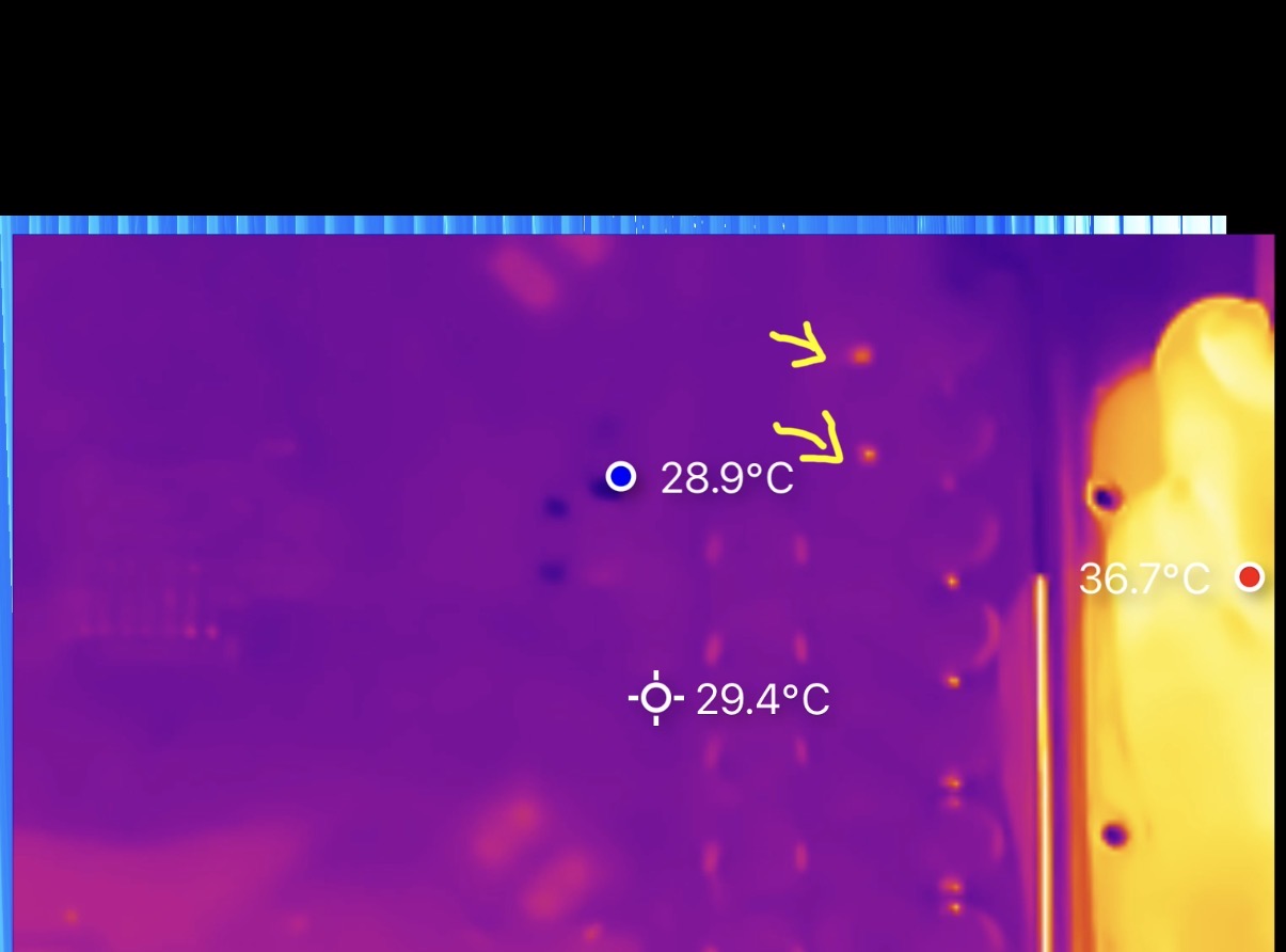
I injected 1 voltage to the coil near F7501 didn’t find hot spot. So I thought that four caps are not shorted themselves. Do I increase voltage to 2v and check? Or pull them off one by one and find which one is short? What else do I have to check for the Dr MOSFAT?
In general: Increase the current not the voltage. Stay at 1V and start at 1A and see what the current draw is. If it reaches 1A and nothing is getting hot, increase the current to 2A than to 3A.
The 5V_MAIN line is feeding the eight VRMs, 5V-USB-C-power-output, Second Front USB power, 5V-disc-drive-power.
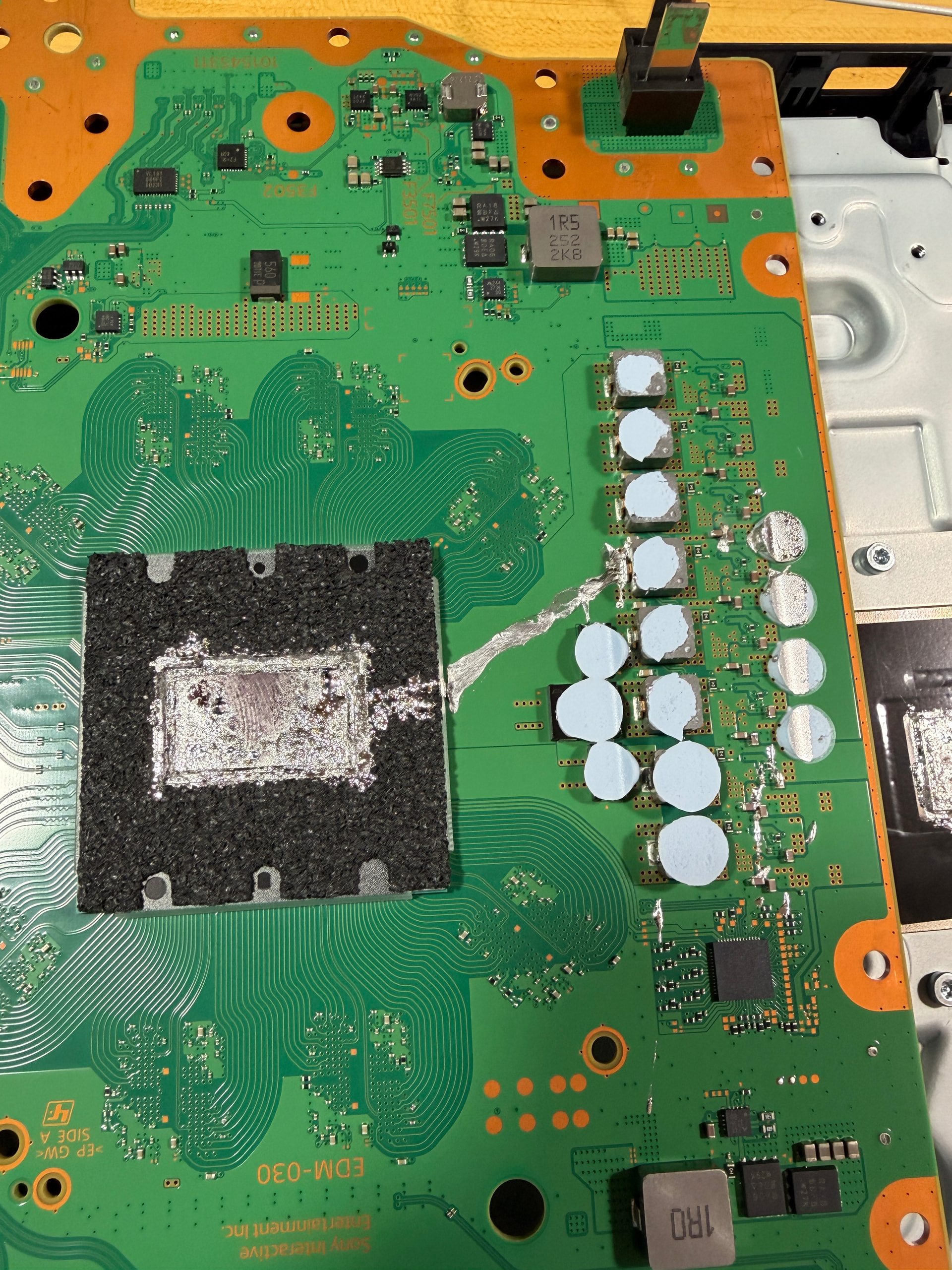
My guess: there are leftovers from liquid metal spill at the VRM which cause the 5V_MAIN to short to ground.
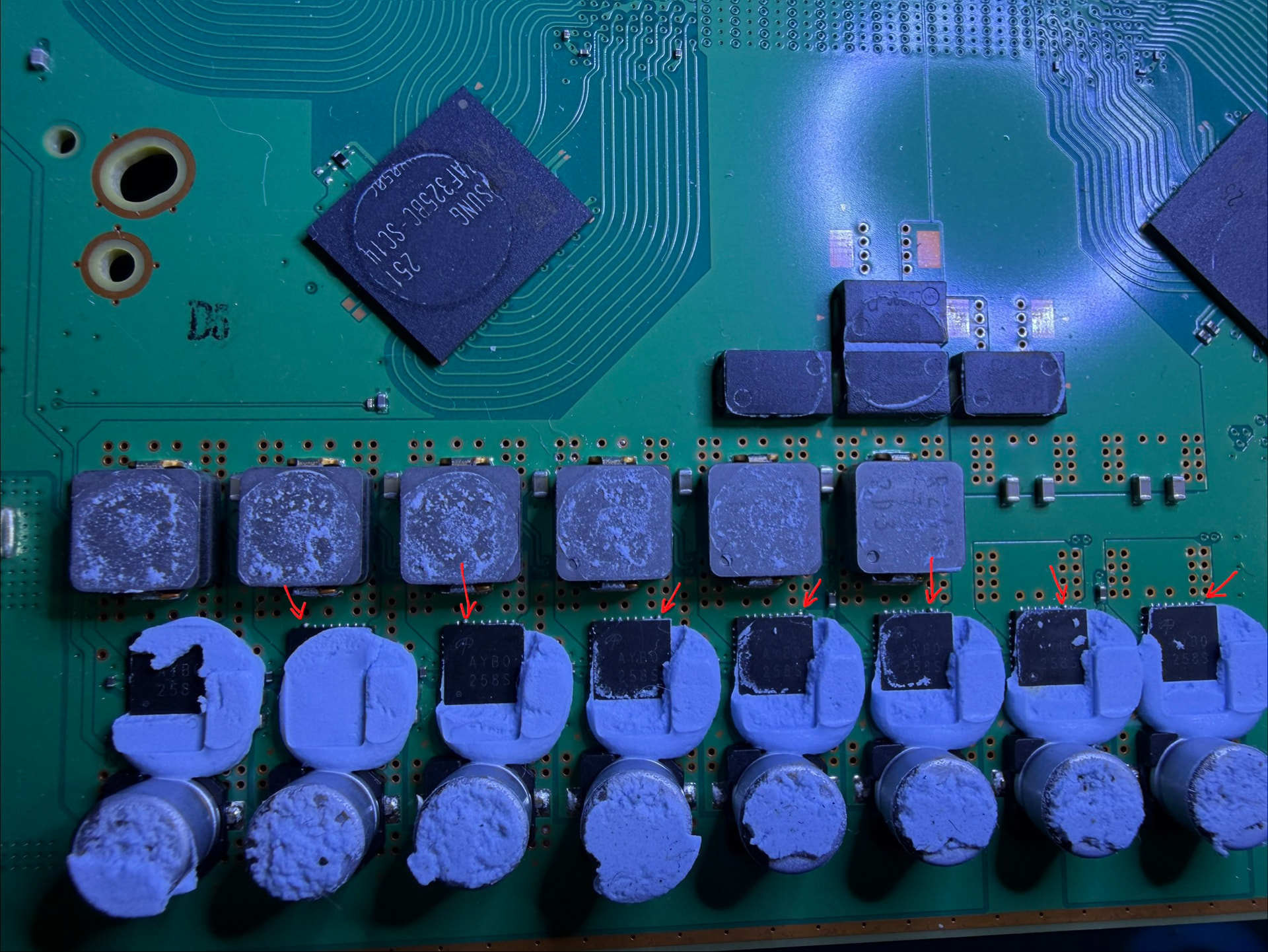
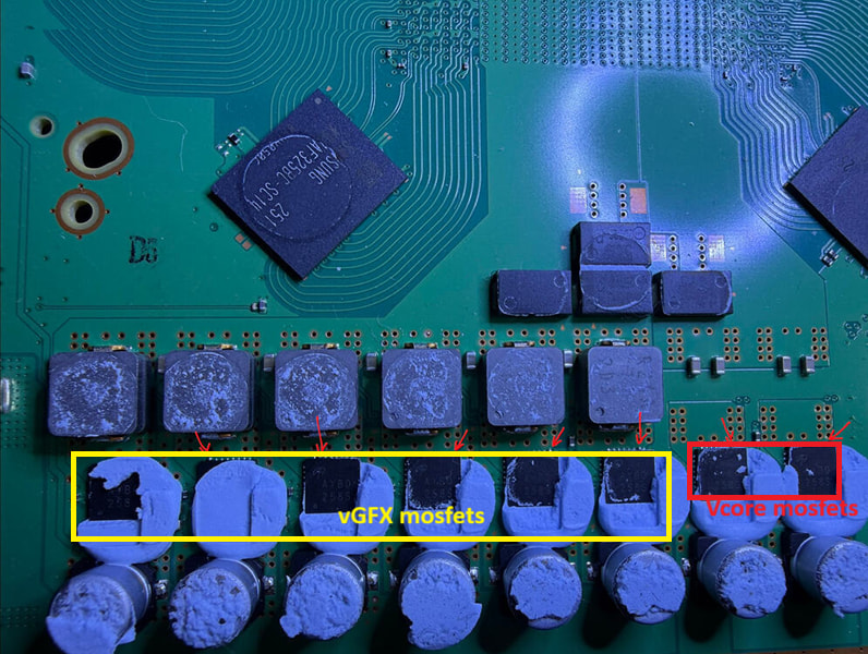
the top two mosfets are for Vcore, they start to work straight after SOC/APU call to turn on, where the rest 6 mosfets are VGFX core, most of them underload when game launch but the rest of time they are in idle stage.
If you dont see any mosfet runs over 80C at idle or 100c under heavy load Game, you might need to look for somewhere else
FYI the solder blob/balls on the output side is kind of normal, I have seen few working/non-working board came like that from factory, there are 8 pins (Vsw_16~ VSW_23) interconnected so likely factory solder paste would eventually came into a ball randomly onto one pin.
Is this the actual state of the backside of the mainboard with liquid metal still spilled over the board?
If so, you have found your issue. Liquid metal is conductive and shorting ever line which get in touch together.
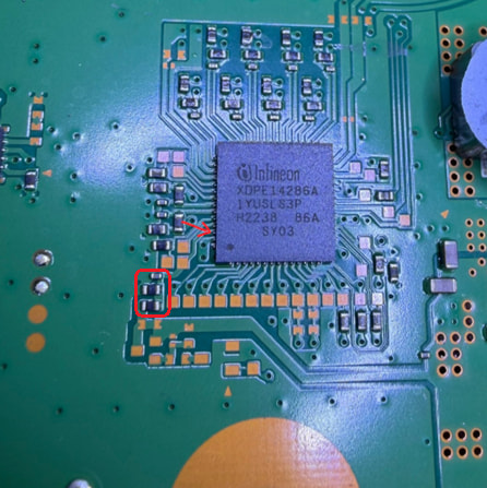
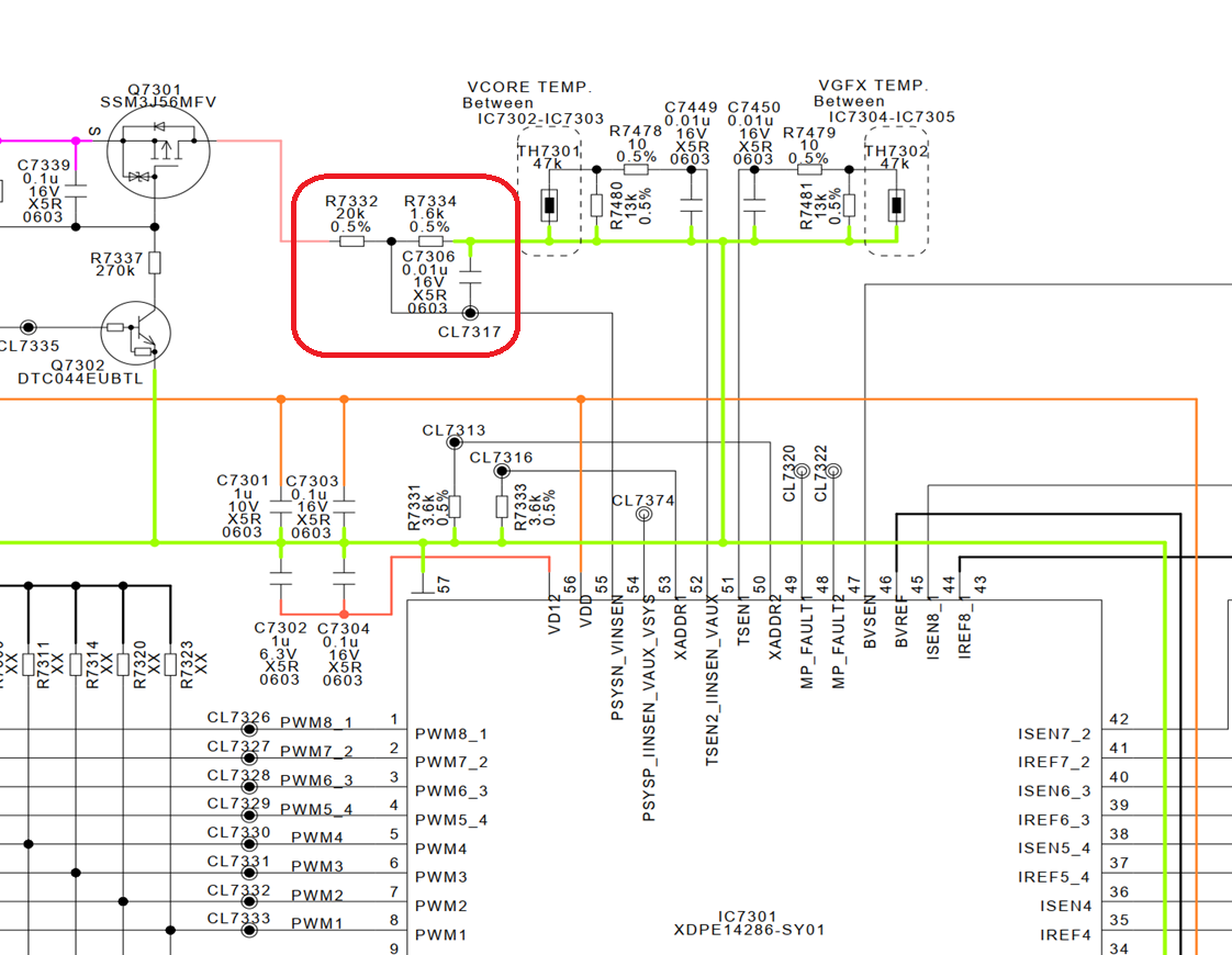
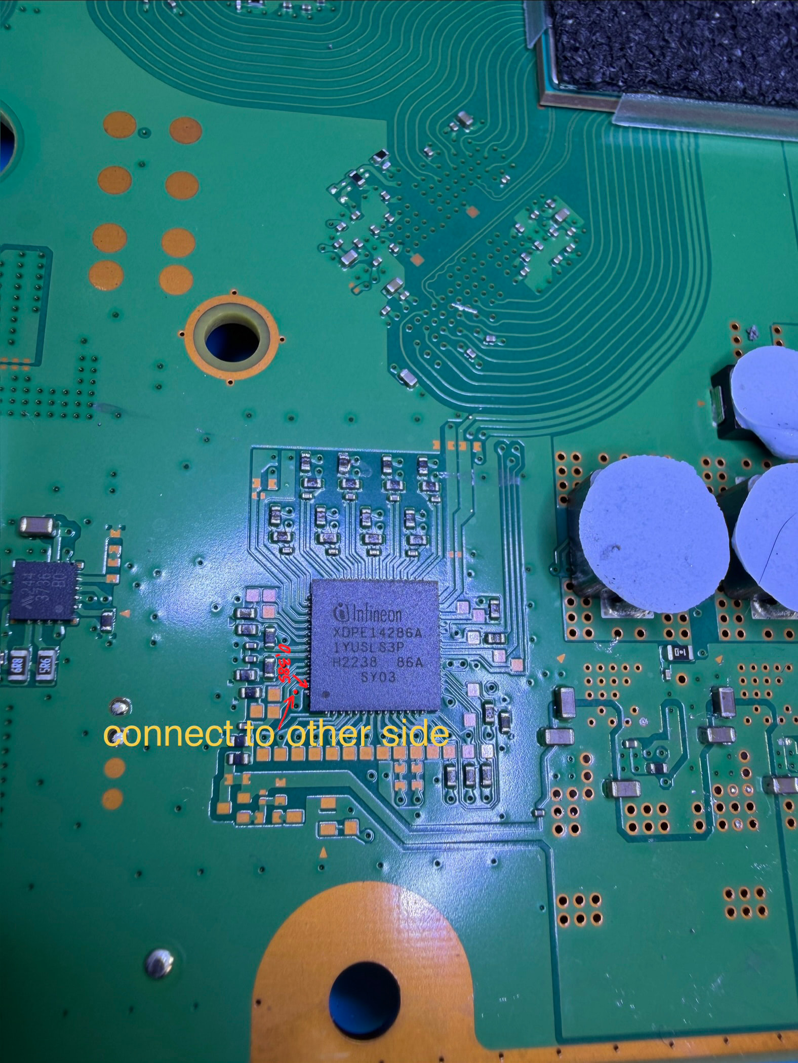
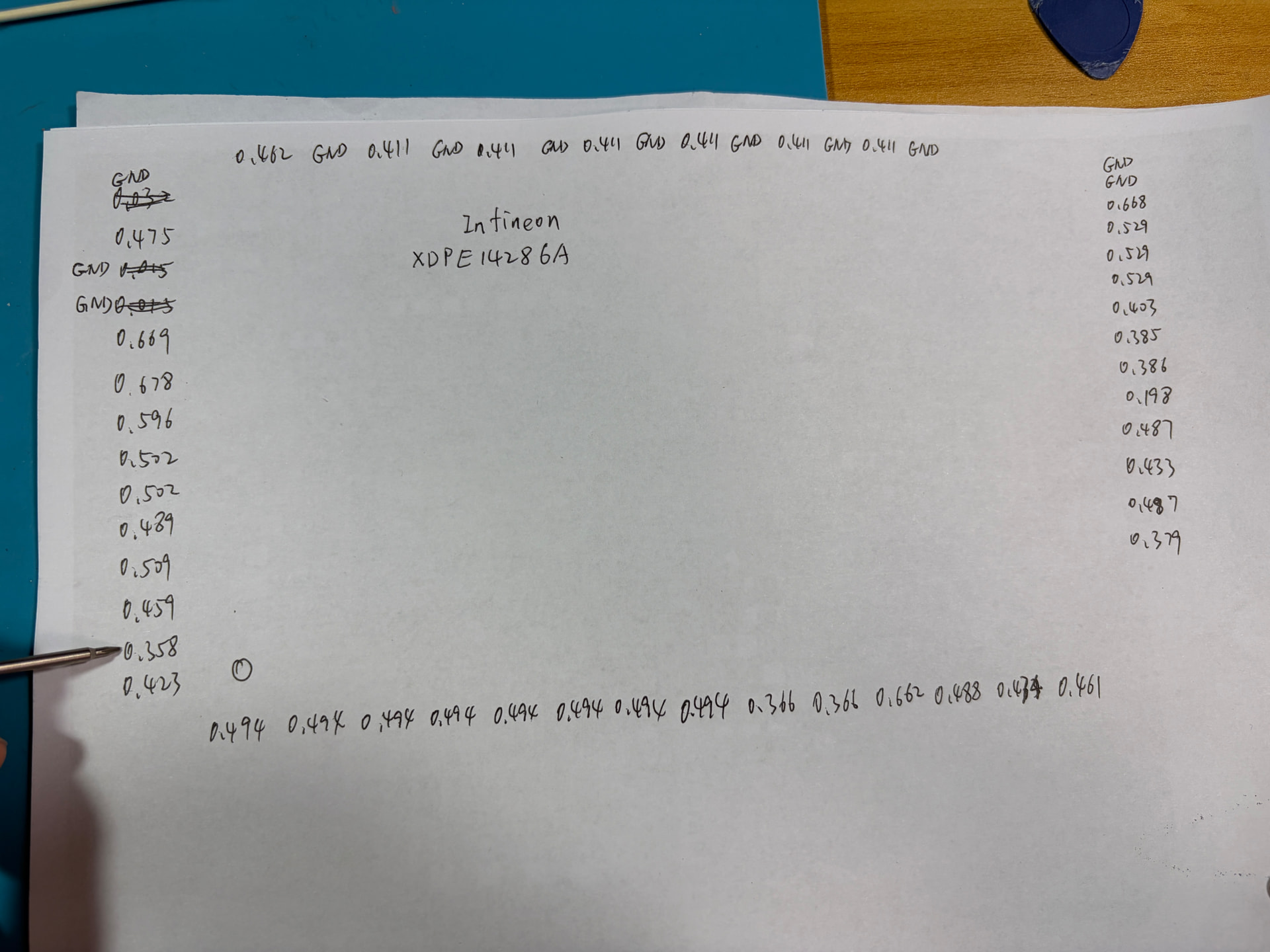
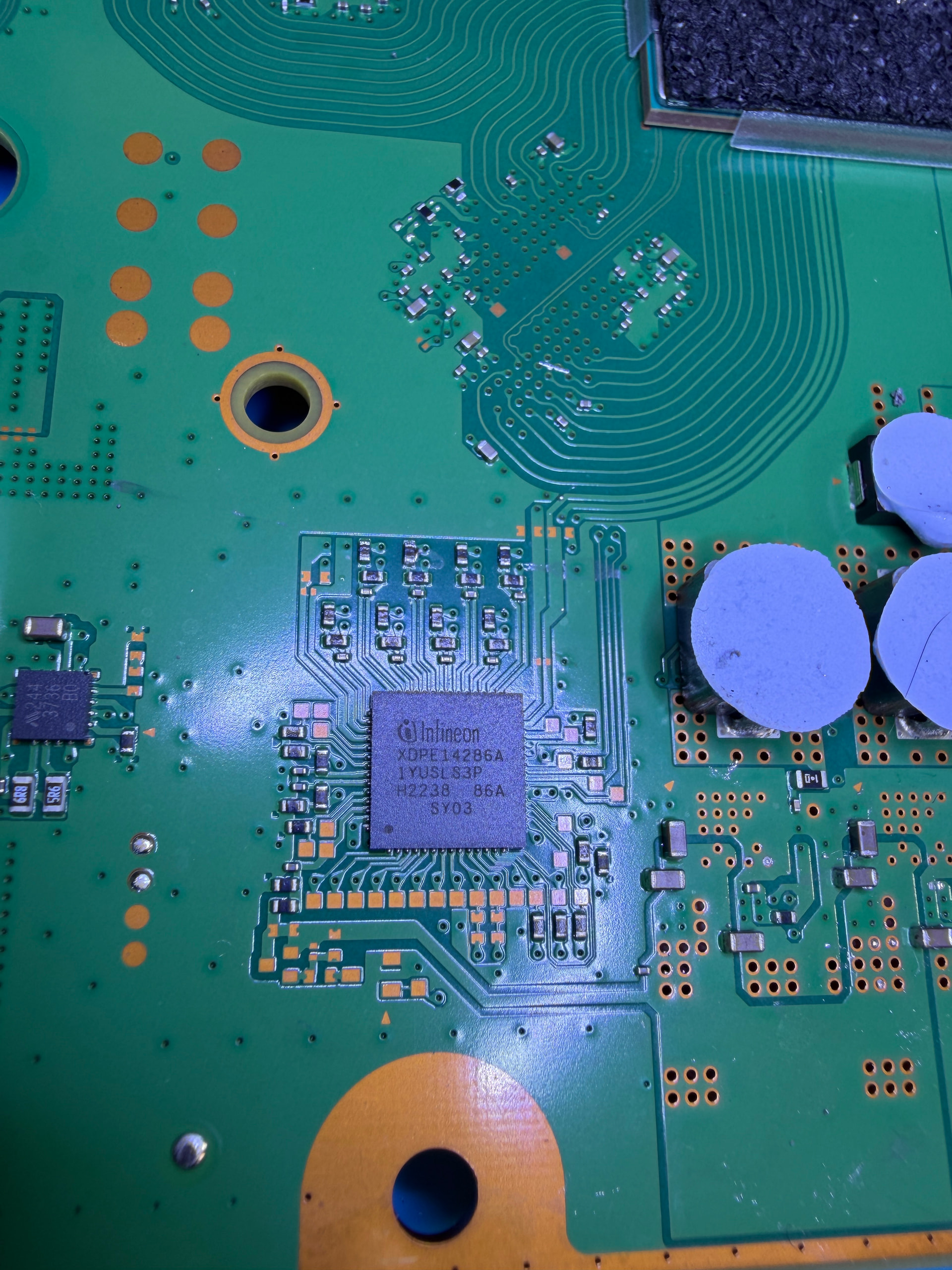
Edited: Sorry, this second pin is actually not normal. Pin57 or Pin2. Diode mode measurement 0.87v voltage drop. This pin is connected to the capacitor on the other side of the board. Good working board should be 0.358v.
I dont any have EDM030 by hand, but from 010/020 boardview, this pin56 is Vcc 3.3v_VRM and it should be generated by a SOT23-5 chip from 5v_main/standby
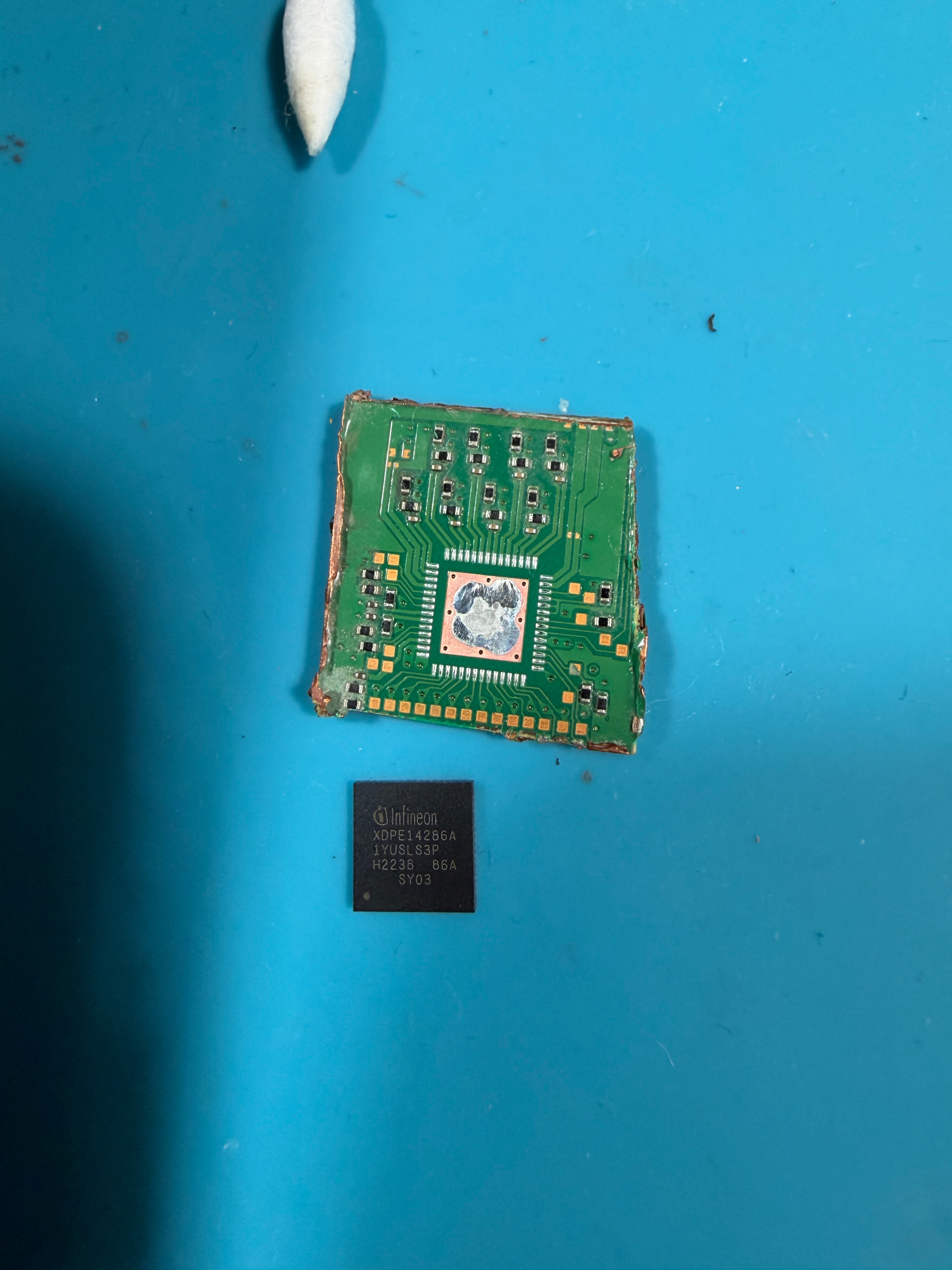
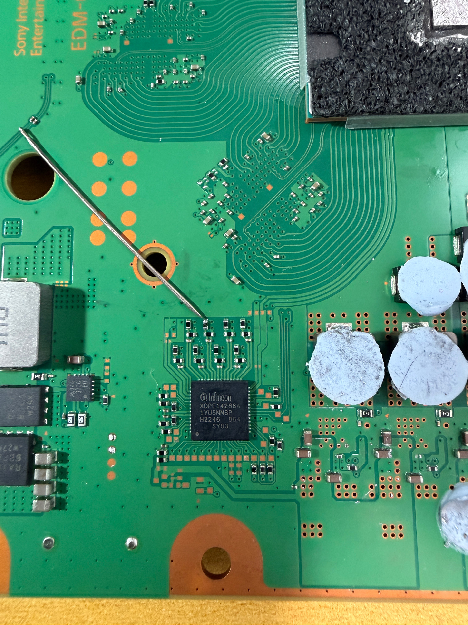
Finally fixed it. Replace a PWM chip from a donor board. Same marking sy03. I believe there are also sy01, sy03 and sy04 in the market and they are not compatible each other. And if it is new chip it has to be programmed?
And I also clean the liquid medal where the needle pointed as I did it notice that at the beginning.