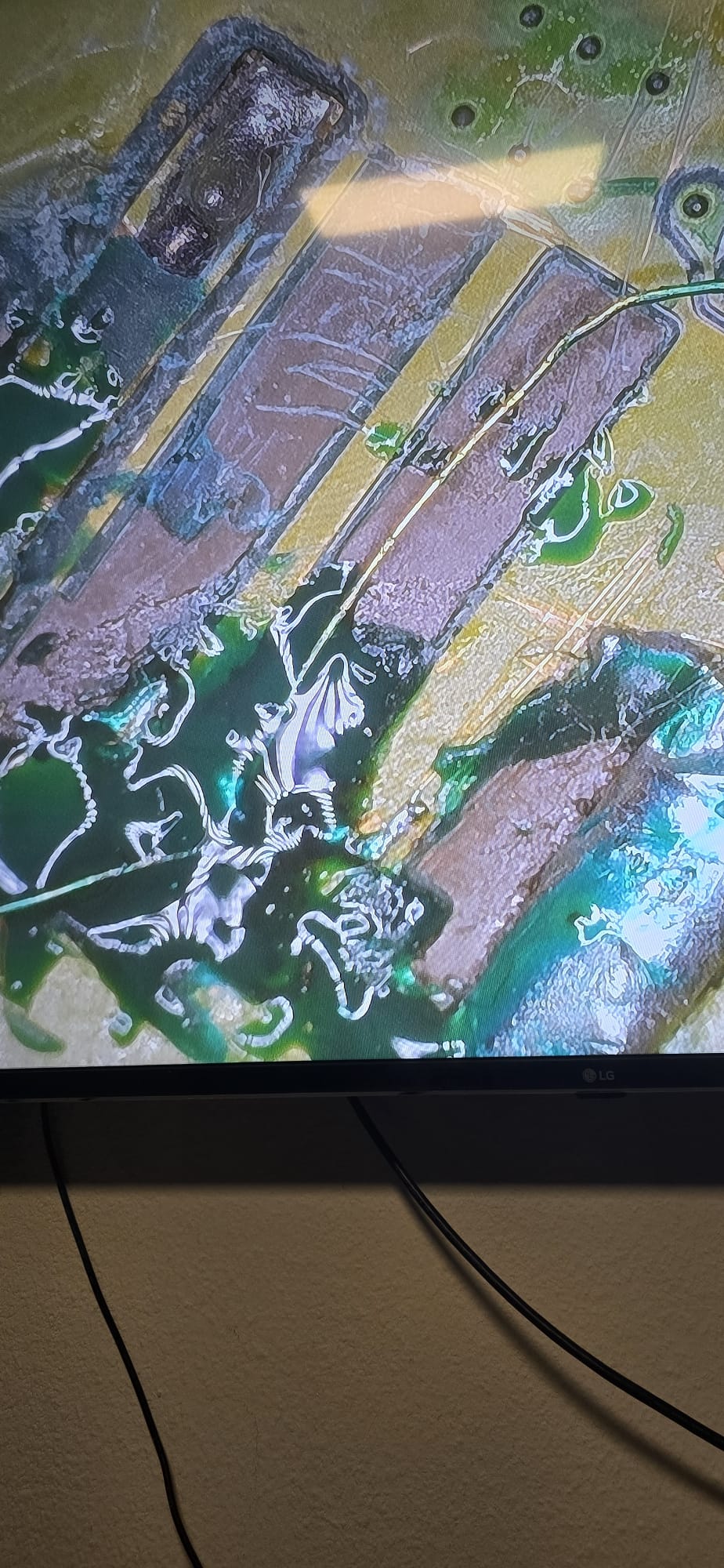
Nice, thanks for the Help. But how the flip can i attach a wire to this…grind it down a little more and try to be lucky?^^
Yes, grind the through hole via from front side a little bit down to expose more pad. then put precise/small jumper wire on it to extend your connection
Okay, will try tomorrow, its gettin pretty late here. Will share result, thank you very much for your input and patience ![]()
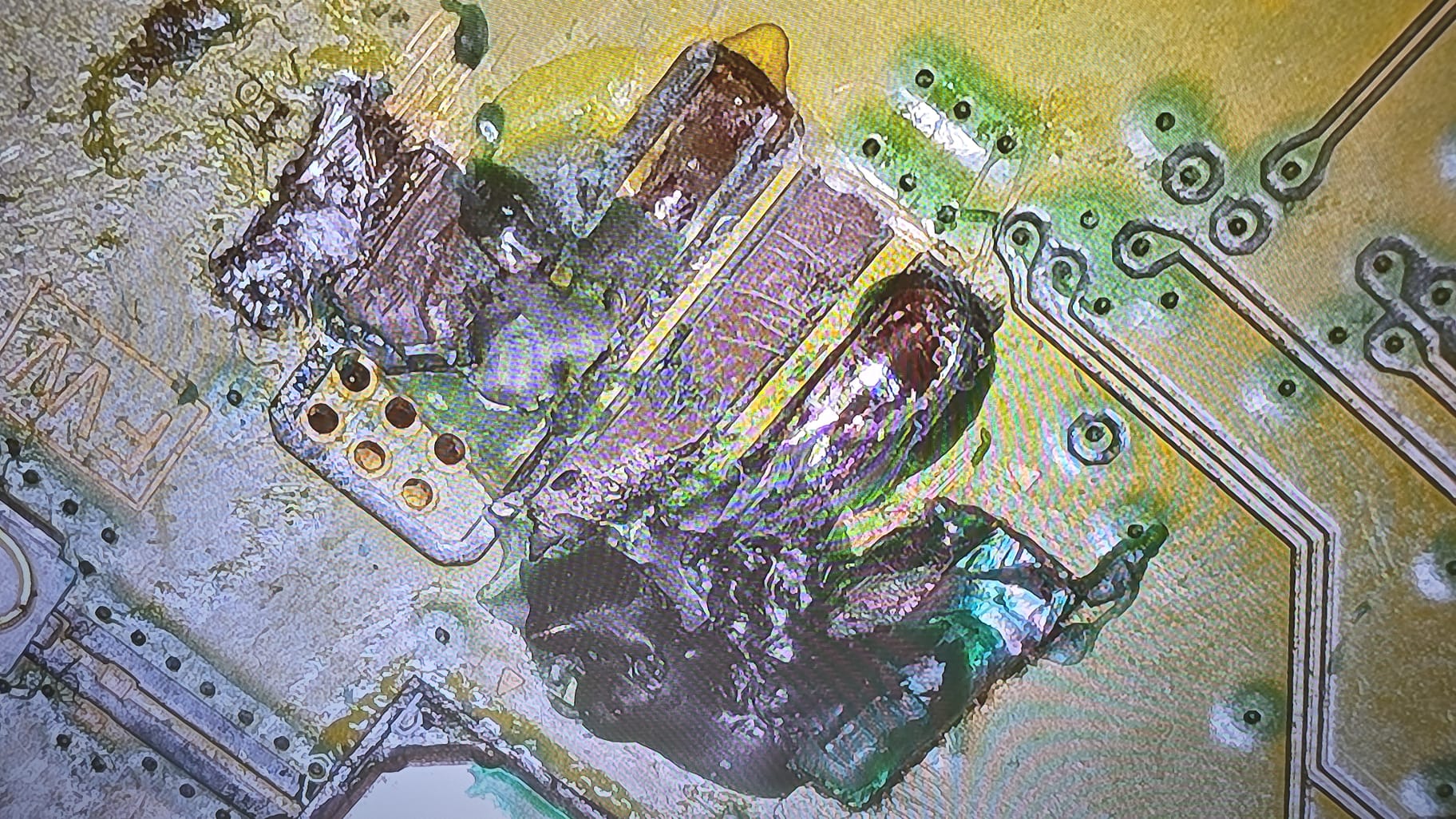
Yes, there for a reason, especially given your wire size vs original pad size (current carrying)
Gladly the 12v pad was saveable. No worries, in process creating a groundpad ![]()
1 Like
imaging why you need to connect ground on your car battery if it is not required.
There won’t be a closed circuit if ground is not connected.(since 3pin fan connector has only one ground pin)
2 Likes
So, connector is back on. Measurements are the same as mentioned above. No shorts to ground tho.Fan ramps up to full even when console is powered down. When i measure diode while powered on, that fan runs normal. I´m assuming its the missing cap on the back maybe?#
you don’t measure resistance or diode mode reading when there is power on the circuit.
Okay, got that. When power pluged out pwm reads 0.575v as before. Any idea what the issue could be? When powered on, in voltage mode, on pwn it reads around 3.2v
If known working fan still do same thing, you are likely having bad connection between southbridge and PWN PIN.
You could add the1000pF cap
to the back but I dont think the cap make any difference to a PWM signal
Thanks, will try the cap tomorrow. I hope i can fix it, doing it for a young guy who got scammed and has no money left for another repair shop. Wish me luck, will post result
I’d provide your readings of the repaired traces to those in the know on all repaired pads/pins to @jkyoho in resistance with black probe on ground to offer further clarity. Your wires and readings seem a little iffy compared to the others I’ve seen ![]()
1 Like
I couldn’t have a EDM010 PWM Pin resistance reading any more since I already de-solder SouthBridge off the board, but on EDM020 and EDM03X board, resistance reading(when fan unplugged, no power cord) are both over 7 MEGA ohm,(10.8MEGA ohm on EDM03X)
Measured like described resistance is at 2.2 MOhms. sadly i dont have a 1nF/1000pF cap, only 10nF. I have a defective ps4 laying around for my next project, maybe i can pull one there…any suggestions where to look for it?
readings are somwhat low (in comparison) maybe suggesting your via/trace repair is touching something it shouldn’t (?) ![]()
At an edm-010 the PWM pin, at the connector without fan plugged in, has ~ 8.5 MOhms. The missing cap shouldn’t make a big difference.
If the PWM pin is powered by the southbridge before the PS5 is turned on, I guess the southbridge is bad. The PWM signal should be low till ‘power on’
1 Like
Did you ensure the via you soldered to had continuity to the other point in @jkyoho image prior to soldering? same again after pad/trace repairs?
Think if it were me I’d undo the repair (and scrape back further if needed to remove potential solder issues) and see if the alt point mentioned has the correct readings relative to ground prior to pulling/replacing southbridge/ If it did, then I’d mask of area at connector and run a wire to the alt point instead.