Begin of the repair is, that I got it with no HDMI signal… at this point it turned on without any problems. but because the display recognized that something has been plugged in but after some seconds showed “No signal” I was unsure if the problem is caused by the HDMI-Port or the Chip. I didn’t want to dissassemble the entire console - especially to the liquid metal - so I ordered an HDMI-Port Tester to check if the Port is fine.
The console was at this point not fully taken apart (took out the Motherboard with PSU , and only took away the cover which includes the “NVME Cage”.
Even in this state it worked normally.
Well it took 3 Weeks that I got the HDMI-Port Tester. In this time the PS5 was in this state as mentioned before dissassembled in a box.
After the waiting time I connected the PSU and HDMI-Cable to check if the problem solved magically itself, but now it won’t power on at all.
welp I checked now with a thermal camera: nothing at all.
The PSU is fine, showing the 12V and also directly on the Motherboard I get those 12V.
Now I don’t know anything at all - never done such a check if it show to life at all, so yea I’m looking for a Dummyguide what exactly I can try out step by step…
It is a common issue that the plastic inlet of the HDMI port come loose and with it the pins to the board.
I would check if the pins are still propper soldered to the pads.
The HDMI port tester is a breakout board?
After plugging in the power cable, the PS5 needs 5-10 sec to be responsive to the power button press. If there is an issue sometimes takes up to 30 sec. And only every second button press triggers a system start.
Hi, sorry for the late response, was now long time ill and finally back.
The PS5 doesn’t power on at all. not after 5-10sec, not after 30 seconds - it doesn’t power on at all.
What I now found out it that the 5V and 3.3V Rails are not available at all.
Anywhere where I check I just can find 12V.
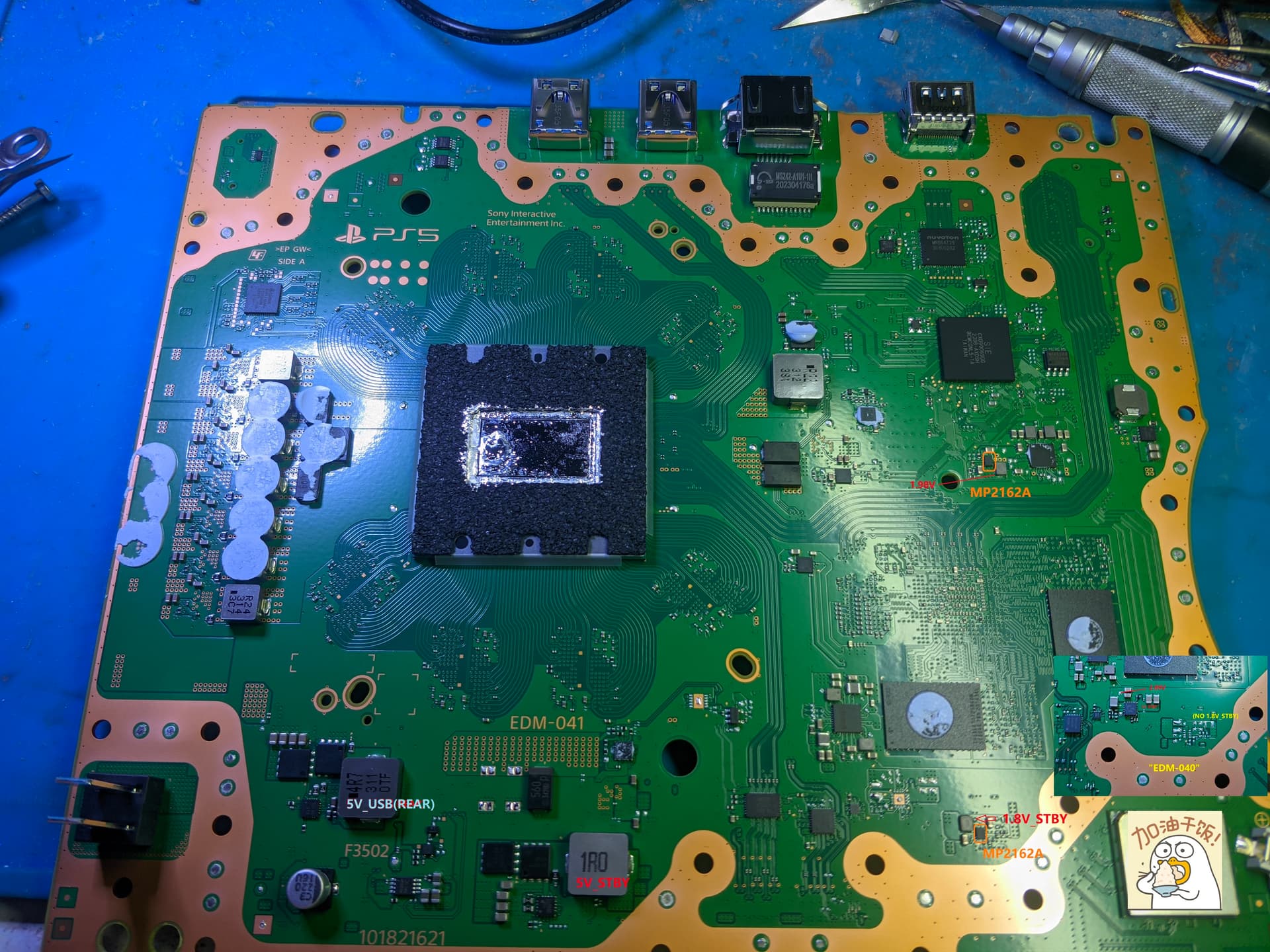
Currently I couldn’t find any EDM-041 or EDM-040 guides, cause the layout is completely diffrent from other guides I’m unsure where the IC sits, which seems to be responsible to generate the 5V rail
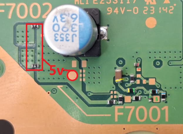
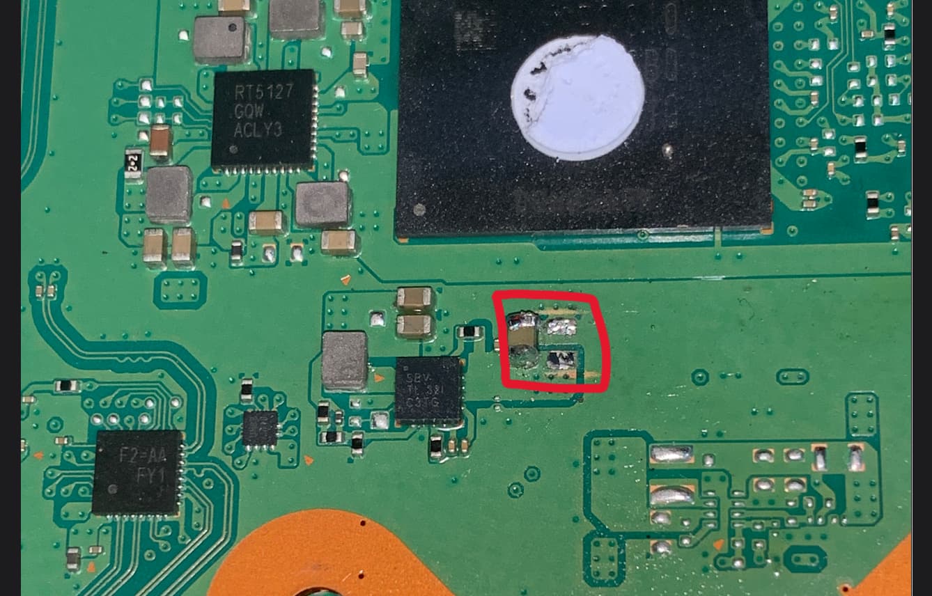
F7001 and F7002 are where your 5v Standby output to the board. F7003 area is where stepdown ic generates 3.3v standby. Check you EDM-041 standby voltage mapping.
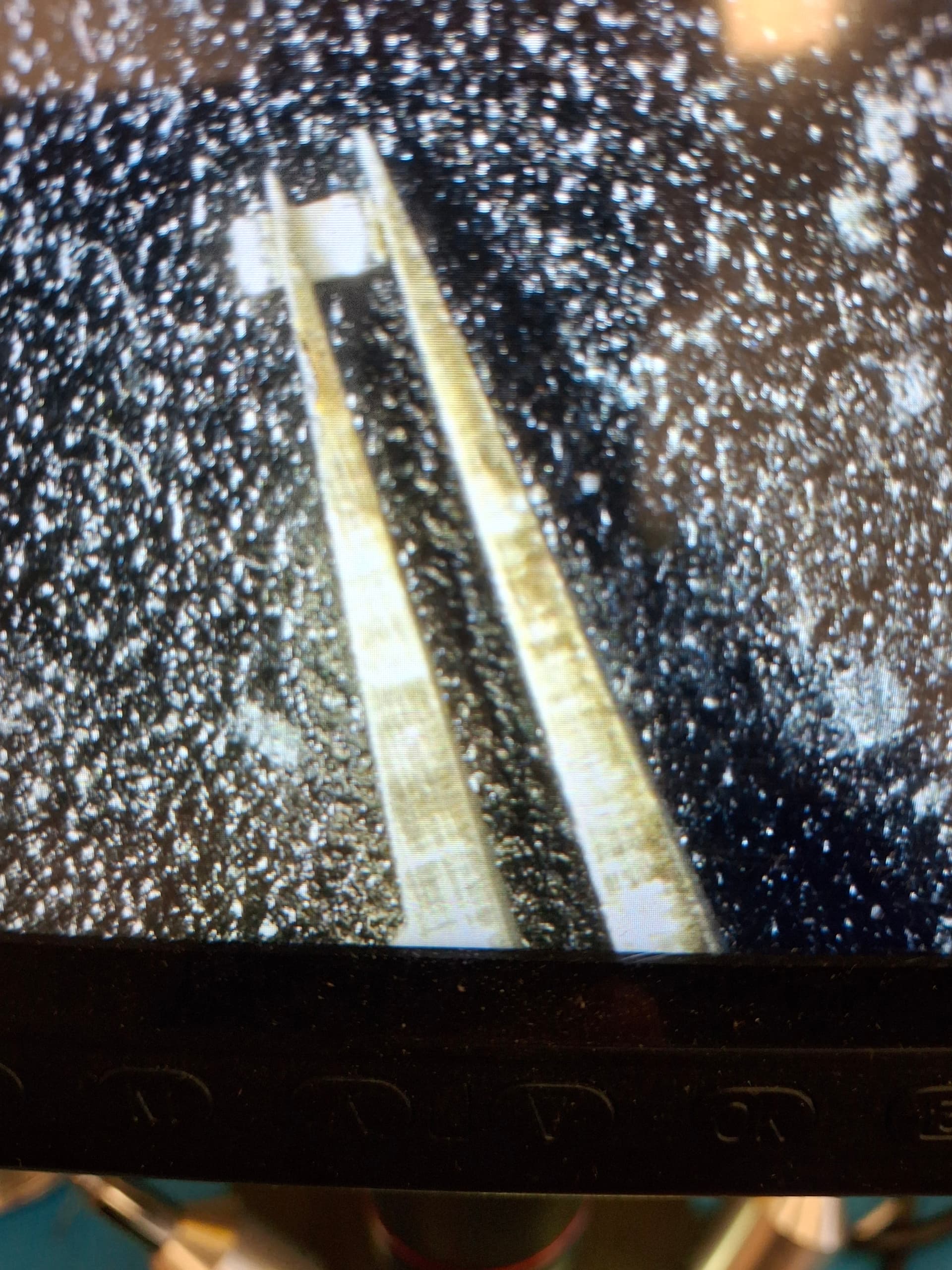
An example picture (Yeah I know in this photo I’m not hitting the measure points, was hard to even get a picture like that) . With the F3501 I get a beep, but noth with F7001&F7002.
it’s a fuse, you dont have tk take it off the board to mrasure. If fuse works it beeps in diode/continuity mode, if it’s ol or no beeps, it blow and needs to replace. Find out why fuses blow is more important in troubleshoot