Hi. Does anyone know where this connections are getting the reading in diode mode from.
Mine seems to have double the value so I thought corrosion under bq chip or connection of the lines but after removing the chip I still get above 1 in value.
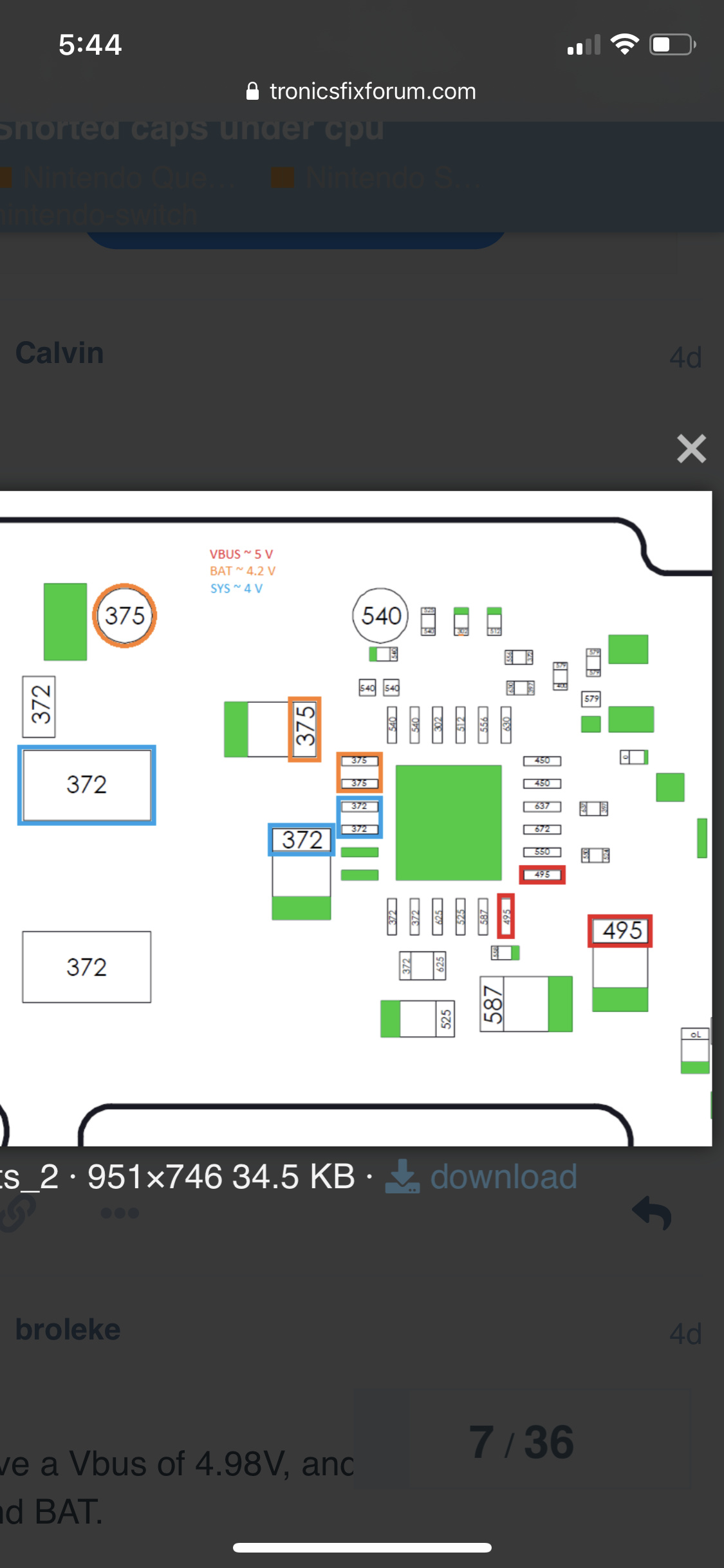
Caps n line in pic reading 495. Mine is all above 1
Please disconnect battery and powersupply from the mainboard before measuring in diode mode.
Put the red probe on ground (not the black one!) and test with the black probe the pins/pads/parts you like to measure. The values may differ from multimeter to multimeter but should be in the same range.
If you switch the probes you get something total different.
My switch is measuring 1.1+. From the pic those points should be at 0.495. I’m trying to figure where those value are comming from , I’m thinking there’s a crossover somewhere. Bq chip is off
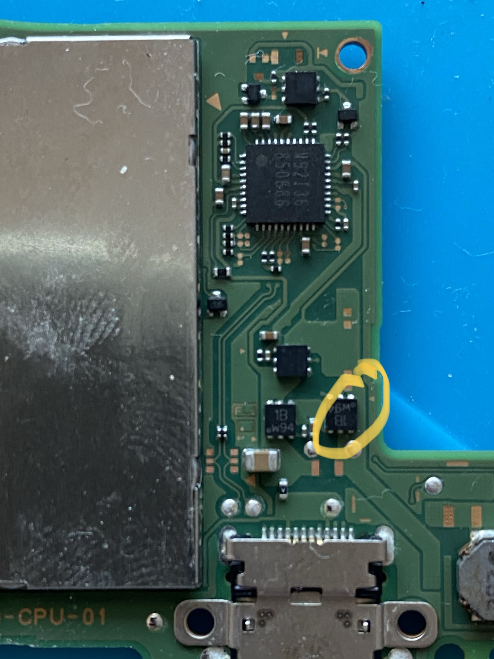
Decided to start removing things. Looks like after removing the 6 legged guy. The measurement on the BQ chip is 0, and two of the legs has the correct measurement now while the other is 0 but I think after I fitted a new 6 legged piece in it should be good.
Will update if it’s the cause. Waiting on my donor board. (A friend borrowed it to take some parts)
GOT similar issue on the BQ Vbus measure today. my reading also 1.1+.
Everything seems charging and working fine, but the Vbus diode reading doesnt match with @Calvin map.
Tried replaced K03&SN1 mosfet. and M92t. same result on BQ pin1/24 1.1+ reading.
FYI, It’s a V2 HAD-CPU-01 board, I remember v1 should have 0.5 ish reading.Not sure what causes this high Vbus reading.
I got a working switch lite came in today and just confirmed BQ pin1/24 Vin line on v2 and lite has different design from v1 Original switch model
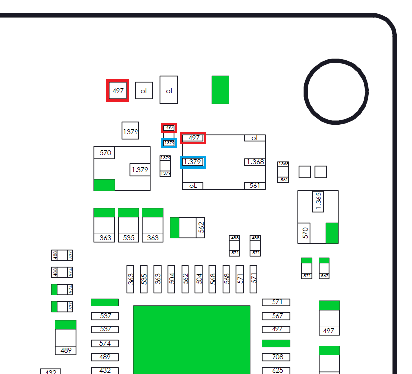
From the pic you can tell Vex line from M92T go direct to top and bottom right mosfet but on v2/lite board, VEX ends on top mos(red square)but not connected to bottom right mosfet(orange square).
That’s maybe why BQ Pin1/pin24 got diode reading 1.1+ rather than 0.49~0.5xx (Vex diode value)
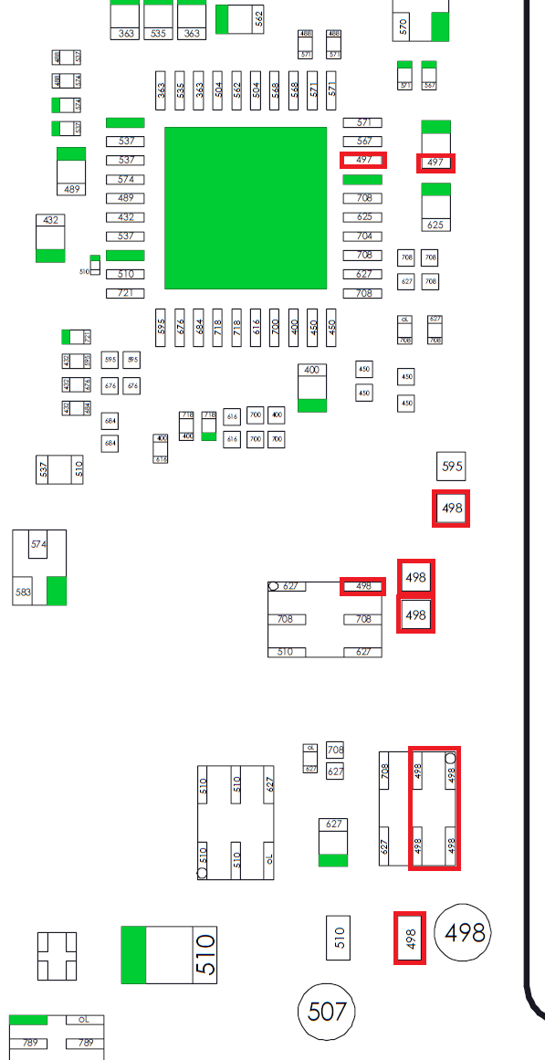
Is it possible that you can measure the diode values of the V2 board of the bq chip and the max77812 chip i have a water damage V2 board i have changed the M92 chip the BQ chip pmic chip the max17050 chip still nothing it takes 12V 0.8 amps drawing if i look via thermal cam the BQ chip is only getting hot