I say “healthy” because it charges fine at 0.48A from 5V battery. No LCD,back light, touch input or docked image is present, so I believe something is stopping it from booting despite the normal power draw.
Now here are some resistance and voltage readings on the various rails:
SYS via pin 6 of M9 = 743/32.7V (this is too low I believe
1V8PDR via cap under M9 = 67.8 Ohms/1.8V
VBUS via cap to the bottom right of BQ = 1.7M Ohms/4.80V
26.7 Ohms on the 2 left inductors next to the PMIC
136 Ohms on the bottom left inductor next to the PMIC
67 Ohms on the top right inductor next to PMIC
The resistance reading on the top left inductor is jumping about from 120 Ohms to 153 ohms
and in between.
——
Are there any other readings that I can provide to paint a better picture as to what’s causing this switch to not turn on? I’ve done all the basic checks.
Since you’re already supplying power to the unit, are you getting voltages at main PMIC? I think you should be getting 1.8v, 1.35v, 1.1v and 1v. Then are you getting voltages on the caps around M92, should be 1.5v, 2.8v, 1.8v and 3.3v. If you’re getting these voltages, try to remove the EMMC then plug into your computer, does it get recognized as RCM under Tegra?
Hi there, thanks for the reply. Ok so 1.8v, 1.35v, 1.1v and 1v are all present around the PMIC. At M9 the 3.3v, 1.8v, 1.5v, and 2.8v are present, these readings were recorded with just the battery connected. With the EMMC removed, tegra does not register it. The computer doesn’t pick it up at all.
You’re able to get RCM with another unpatched Switch right? Just want to rule out any issues with drivers / USB cable and your PC.
Yes, I regularly jailbreak switches so everything is in working order as far as the computer side of things.
You’re testing with a known good LCD / backlight right? Have you check done a visual check for shorted pins on the LCD connector?
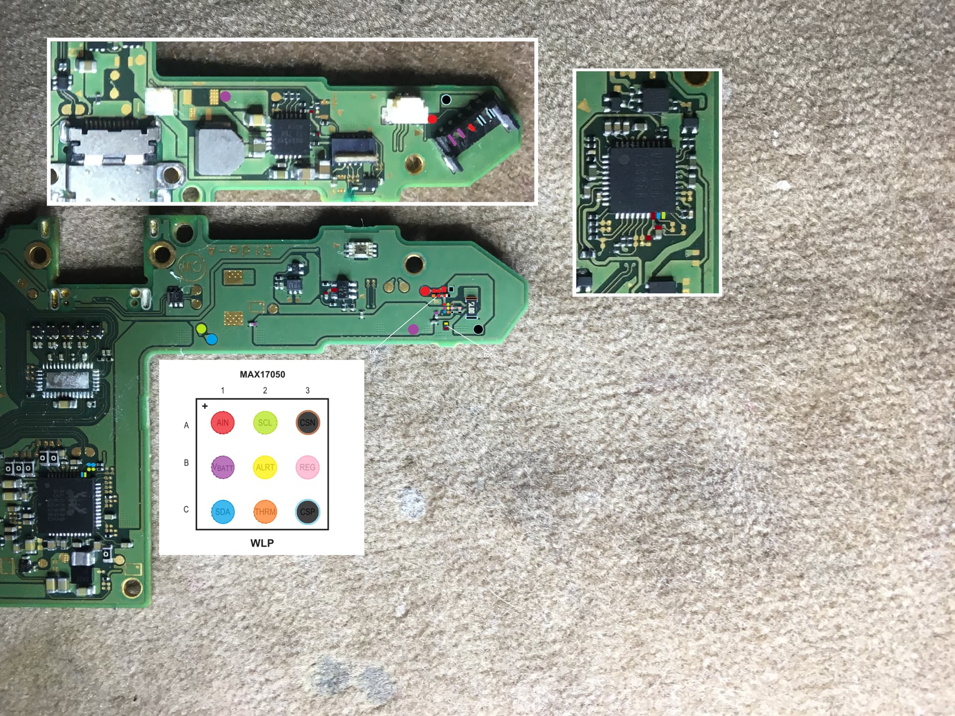
Given that you don’t have any shorts on caps, you don’t get RCM recognition even with emmc removed and you have all voltages present (CPU and GPU buck should output I think ~0.8v also but I don’t think you’re getting that given that you’re not even seeing nintendo logo) and that everything else on board looks good, I might start by checking diode readings on fuel gauge (search site). Bad fuel gauge chip is infamous for halting boot.
Yes the LCD is a known working LCD. I’ve also replaced the LCD connector, making sure that all pins are making solid connection with their respective pads.
You are correct, both the CPU AND GPU bucks don’t output 0.8V but I am measuring 3.7v on what I presume are the inputs?
Diode readings around the fuel gauge seemed normal. I don’t have a diagram to compare with but a donor board near by had similar values. Also in voltage mode I read a 1.8v on vbat (B1) and 2.11v on reg (B3).
Any indication of what caused it to not turn on in the first place? Ive seen a few of these with your symptoms but they had severe water damage (like a switch that was in a flooded warehouse), never really got around to figuring what caused boot to hang. Maybe others can chime in but if you dont see anything obvious then i would swap fuel gauge and see what happens. If that doesnt change behavior then probably ram/soc.
Was a switch I bought off ebay. The listing said that “It was sent off to have the case switched out for a new one and when it was returned it did not turn on or respond to any sort of attempts at repair”. When I opened it everything looked fine except for the LCD FPC connector, which had the plastic flap thing detached and some pins that may have been touching. In hind sight I should’ve verified any voltage rail pins on that connector to see if a rail received an amount of voltage it shouldn’t have. @Severence said (this is from memory) that the LCD connector gets voltage from 1V8PDR as well as the LCD driver IC (which I think receives around 5v?).
I replaced the fuel gauge which produced no change. Now that I think about it, I wonder if the SOC received to much voltage or if the 8316 LCD driver IC took the hit, because it doesn’t output voltage. It’s input is fine but it doesn’t output the -5v/5v.
Measure the 4 pads next to the lcd driver ic, the lcd ic gets enabled by SoC with 1.8v via those pads. The lcd driver turns on upon boot (although im not sure if you first need cpu buck to produce 0.8v first or not). The lcd driver will then turn off (1.8v enable goes away) when lcd turns off / sleep mode. To remove any doubt you can attach the power ribbon cable, hit the power button then measure the enable pads. If 1.8v is not present the lcd driver wont produce output voltage. You can also measure those voltage lines on main pmic and m92 to confirm the console is ‘on’.
To clarify my prior post (it wont let me edit it). If you dont get 1.8v enable at lcd driver ic something else is halting boot and points back to the cpu buck, soc and ram since you have all voltages at main pmic and 3.3v and SYSRAIL present. You can also remove the m92 and p13 and boot from a good battery to rulet those out as well. I dont know of a way to test whether the SoC is good or not other than testing for shorts (although i think soc could be dead even if no shorts are present).
I get no voltage on these output pads. I’ve replaced it and it made no difference.
You mean no voltage on the pads that provide 1.8v enable to the lcd driver right? If so, then dont think that is an issue since something else is causing it to not boot. I read somewhere that you dont even need 0.8v from cpu buck to be detected for RCM, that RCM recognition only requires the most basic components, which is SoC and ram and usb port (this is good right?).
Maybe try to put pressure on SoC and ram prior to connecting usb and see if RCM is detected or not, possible it could be a bad solder ball joint.
Otherwise im out of ideas, but im a relative noob at this (picked this up as a hobby). Maybe @Severence can chime in if he has a free momemt.
So you have a short here on your 1V8PDR… should be in the K’s at least which could be any number of things
What’s your resistance to ground on SYS?
Pin 6 is 3V3PDR not SYS 
Resistance to ground on SYS rail is 02.0M ohms. Surely this is very high right?
That’s fine
What’s the resistance to ground on 3V3PDR also?
Yeah that’s low too, I’d pull M92 and see if it clears these “high” shorts to ground on these rails, if not I’d see which area of the board focusing on 1V8PDR what represents the lowest reading to get a better idea of where the culprit is. Failing that PMIC would be my best guess… but that is just a guess