Shorted caps under cpu

I will remove the usb port then.
How can I test the diode that seems in bad condition ? continuity ?

I would test the esd protection ic in diode mode.

1 Like

Sorry, Been having a hard time positively identifying the “ENXX” IC

On first glance it appears to be either TPS63025x or TPS63024x but there are some inconsistencies, I’m not too worried about the markings on the IC not matchinng the datasheet as that’s typical but the physical dimensions are a hair different… i measure the one on the board at 2.30mm x 1.70mm

Even so, the application circuit lists identical support components (inductor, caps etc) compared to whats on the board so somewhat confident.

OnSemi and ST have converters/regs in similar packages with the same pin/ball count and pitch etc but as far as i can tell none of them were a match pin definition and layout wise.

I’ll finish buzzing everything out on a donor tomorrow and after will hopefully positively ID the IC as a result, afterwhich i can give specifics of what/where to test.

Would welcome any thoughts though from others in regards to “ENXX” identity and if I’ve missed something obvious?

@broleke In the meantime though, is there any chance you can take a pic of the boards rear in better light at some point? there are a couple of other things catching my eye but it’s hard to tell because of the photo quality and lighting.

Thanks you both for your help.

I have 1.5V in diode mode between CC1 and CC2 (just on top of the CW writing).

Please unplug the battery and the charger, put the red probe on ground and with the black probe test the six legs from the ic and compare the values with them on my post.

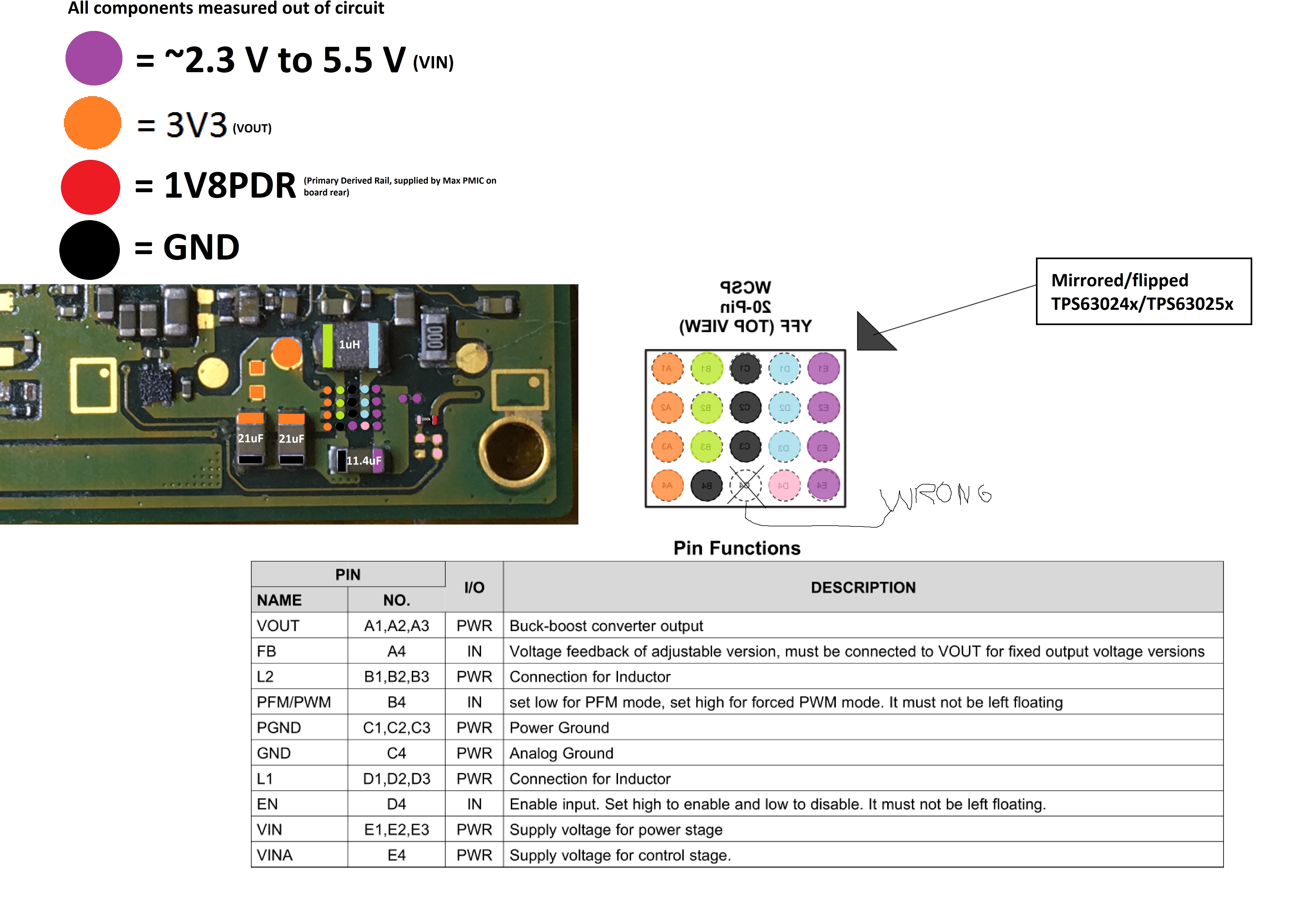
Apologies, I made an error earlier while viewing the datasheet… In order for TPS63025x or TPS63024x to be the correct IC/s the Pin layout would have to be flipped (and even then, there’s an issue)

Even so, I’m pretty sure the “ENXX” IC is a TI part and is either a custom variant of TPS63025x or TPS63024x or a rebadged variant of another TI chip spun off from this series (which I’m unable to find) - Checking the various signals on my oscilloscope mirrors the figures in the datasheet 1:1 including inductor freq.

Though if I’m wrong I’d be happy to be corrected. As ST has some very similar specced packages but none were quite right when looking at my scope, given that though, it’s possible it could be from another manufacturer.

Regardless your welcome to see my crude mess here

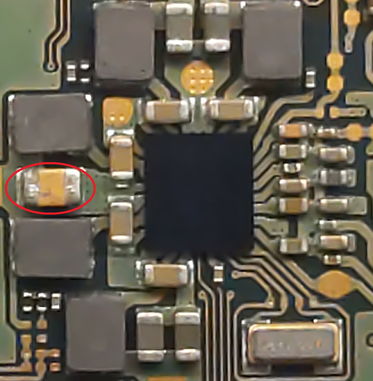
So @broleke in your case, you could connect battery, prompt to boot then carefully measure voltages at the following points and post results.


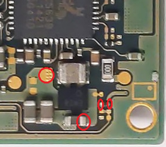
Afterwards, disconnect battery power and take resistance measurements at those same points relative to ground both polarities.

And also resistance measurements on the following capacitor (both polarities)

Here the measured values in diode mode (from top left to bottom left)
0L
0.4795V
0.0000V
0L
0.4788V
0.0000V

If checking the 4 probe pads (from top left to bottom), I read:
0.3872V
0.3872V
0.4783V
0.4783V

Thanks and sorry about the next naive question, but how should I measure something on side-A ?
Do I only need to connect the battery wire and short some pins on the power button connector on side B ?

The resistance for side-A are (from left to right):

  • 1.5MOhm (fluctuating down)
  • 253Kohm
  • 149KOhm
    And for the capacitor next IMX7, 43ohm and 50ohm (reverse polarity).

The reading are fluctuating a lot (decreasing continuously), this I cannot explain… but my electronic skills are somehow really limited.

Values seem fine afaict

No worries,

If I’m understanding the question correctly - “how do i prompt the console to boot with only the battery connected” is how I’m interpreting it, but correct me if I’m wrong?

If you still have the USB connector present on the board you can quickly plug it in whlie the battery is connected then after unplug the cable, the console will remain powered on until battery is unplugged or drained.

If you want to play it safe because of the dodgy USB connector, then you can promt it to boot with just the battery and power button/volume flex connected and hit the power button

If you don’t have a spare flex out of assembly you can also alternatively just bridge one of the four pins to ground on the power/volume flex connector. I don’t remember the pin order off the top of my head but ones ground, volume+, Volume-, power. So you just touch the ground pn to the power-on pin with tweezers… there’s only three choices here so you’ll get the right one in the end :smiley:

Assuming this is from the larger test pad? could really do with the opposing probe polarity readings here.

I have an idea whats iip but i’ll wait til you get those voltage reading first.

From memory that’s good, and we can rule that rail out :slight_smile: just wanted to check as this and other caps on the rail looked somewhat dull

I wouldn’t worry too much about this, your are in effect charging up components when measuring on the board in resistance/diode mode switching/changing polarities can exacerbate the problem depending on whats in circuit

Don’t have the options on any of my meters so I’ve got no clue, but might be worth checking it LoZ/Auto Impdenece etc isn’t turned on/off. Might resolve or improve the situation

Man…talk about being completely wrong…forgot about Richo :roll_eyes: :roll_eyes: So i take all i said about it being a TI part back.

The IC is a Richo - RP602Z330C
more info here n-redc.c o (dot) jp/en/pdf/mark/me-rp602z.pdf
Dimensions are inline with what i measured earlier.

Unrelated but, renesas appear to have a pin compatible part also on first glance

So other forums concluded the IC ENXX was a headphone amplifier. Sounds like that’s not the case?

Yeah, it was a user here who said it but, was very mistaken, it’s 100% a Richo RP602Z330C

If that particular user swapped it for a headphone amplifier i would guess…bang :wink:

Sorry Severence, I’ve been really busy and could not look at your messages before.

Which measurements should I be doing now that the Richo thing has been found ?

Thanks for the tip.
Unfortunately, it seems I have not such feature on my DMM.
[860.cdr (brymen.eu)](brymen .eu/wp-content/uploads/biall/102093/102093.KARTA_EN…2015-07-09.1.pdf)

No worries,

The same as before, the 4 points around ENXX highlighted in the pic earlier, and if you can overlay your measurements in the pic too it will probably save some confusion

And be really carefull with your probes in this area

I’m sorry I forgot to answer this thread.
I lost interest (and mostly time) in this project and sold the switch for spares.

I’d like to thanks you all for the help you provided here !

Hey,

I’ve got the exact same Brymen meter and I’m having the same problem with resistance measurements fluctuating wildly. Not sure if this is a design flaw.

I tried a cheaper unit recommended by @Severence (UT61E) and I’m getting far more consistent readings.

Go figure.

hello,I have a switch with wifi probrem and not power on,I want to repair it myself,would you send me the full diode mode diagram? my email is 361404961@qq.com。thanks a lot!best regards!