Hi all, I have a few switches and switch lites to practice repairing on.
I have some experience with board repair but it is limited. Had some success repairing two already by replacing graphics IC and M92 etc but this one is confusing me.
The USB C port was damaged so I removed this and tried to power it but it gave a 2001 error so I replaced the M92 and this got it booting to the Home Screen.
Next I replaced the USB C port (first one) I was heating the board from underneath and this has appeared to go well but I did knock a couple of components out of place which I’ve now put back but I have a short where I don’t think it should and certainly doesn’t on my other switch that works. (Older board revision)
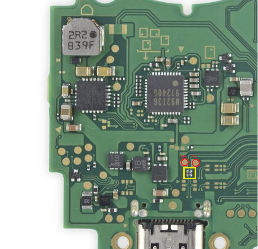
The really odd thing is, I’ve taken this part off the board and the short disappears but in testing the chip it’s also not shorted across those pins. Put it back on and off twice now just to be sure no bridged connections but still shows a short as marked on the pic. I’m don’t want to plug power in with this being unanswered! Any ideas? Confused!
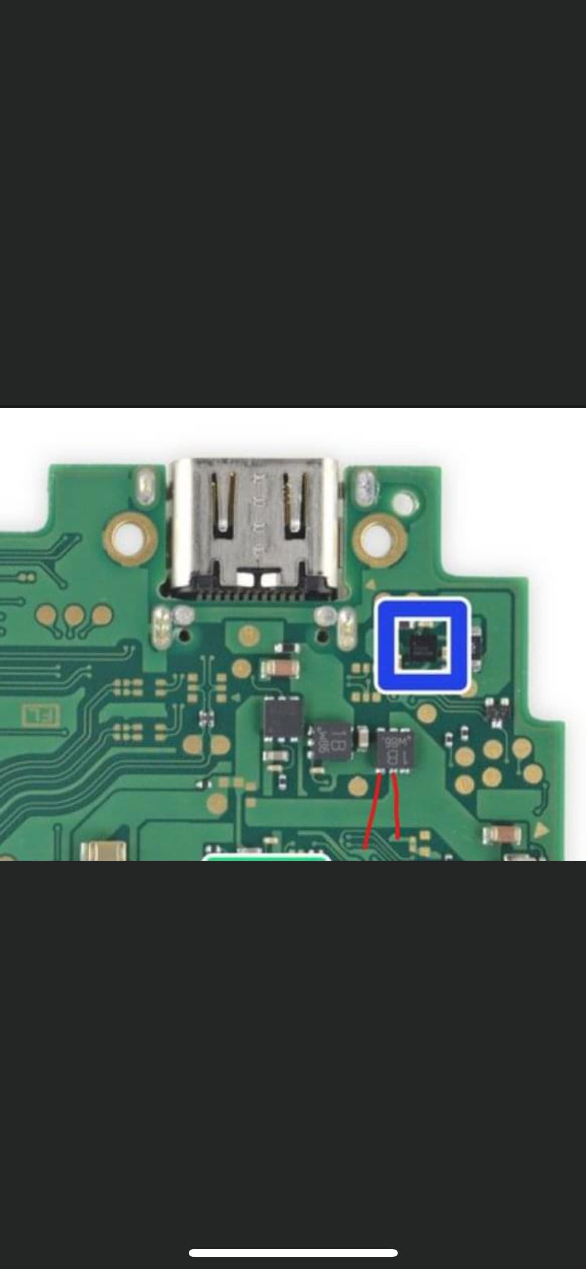
You are having the battery fuel gauge ic knocked off. You need to reball it and put back.
And the OL you got from the usb port is D+,D- data line.
Check from the back yellow circled filer to see if it has continuity fom top to bottom
How important are filters? I don’t have any spare switch boards but I have iPhone and iPad which have the same size filters but values could be different. On a working switch board the filter measures 4.7 ohm on the board whereas the iPhone and iPad are measuring around 3.1 ohm on the board. Can I use these?
Based you have a 4ohm reading on the filter instead of 0~1 ohm.(9~12ohm at100Mhz from spec). I guess your short measure probably wrong as well. that fets from that two point are Source on the left and Drain on the right . If you put red prob on the right, you may have different reading.
Thanks jkyoho, really bizarre but the short is now gone without me doing anything. Maybe cleaning the whole board removed some random solder ball or something… I attempted to reball that fuel gauge IC but while cleaning it, one of the pads came clean off so waiting on a replacement.
I was going to do that but the CC1 and CC2 lines have continuity from my USB C test board all the way to the M92 and D- and D+ have continuity from the test board to the test pads on the board. Do you think it’s still worth reflowing or does the problem look like a dodgy M92?
You were right Reflowed the USB port and I now have charging both ways Managed to knock off the damn fuel gauge chip again though Is it 0.25 balls for this?
This may be a dumb question but I thought testing with my USB C breakout board would work. I have A1-12 and B1-12 and one way up I’d get continuity on the test pads to M92 for CC1 and D- / D+ and power and the same for the connector the other way up for the above and CC2. This matched a working Switch. What did I miss or what was I doing wrong here?
I would guess they’re closer to 0.3mm/0.35mm but tbh I haven’t checked as I use stencil and solder paste (and would suggest you do the same )
Instead of checking for continuity, check resistance instead (or look at you meter screen while checking continuity if it provides an ohm redout) as an intermittent pin (which might just be touching the pad) might be high resistance but low enough to still trigger your meters continuity mode
Thanks, had a crack at reballing last night. 1st attempt sucked so tried again and got it pretty good. Got it on the board and realised I’d knocked off a cap. Went to hot air it back on and blew the IC off again Will try again today. First time reballing in about 5 years. Last time was an SMC.
Yeah good shout as I was only relying on the beep. My theory is correct with the way I was testing though, right?
Sounds like your air flow might be a bit on the high side
Right, checking continuity from a USB breakout board to the lines corresponding destinations on the board would normally validate the USBC pads integrity (provided the lines aren’t high resistance as a result of a bad pin/pad connection)
pitch is generally referring to the space between balls and not the ball/pad size, if you selected the wrong stencil the holes wouldn’t line up, if they did then it will be fine with the resulting ball size being correct… that all being said, solder paste will always result in smaller balls vs using preformed, this is as a result of the paste flux content and stencil thickness variations, I’d guess about -20% minimum size variant which isn’t a huge deal on these small ICs with ball size consistency being the more important factor

 Reflowed the USB port and I now have charging both ways
  Is it 0.25 balls for this?
 Will try again today. First time reballing in about 5 years. Last time was an SMC.