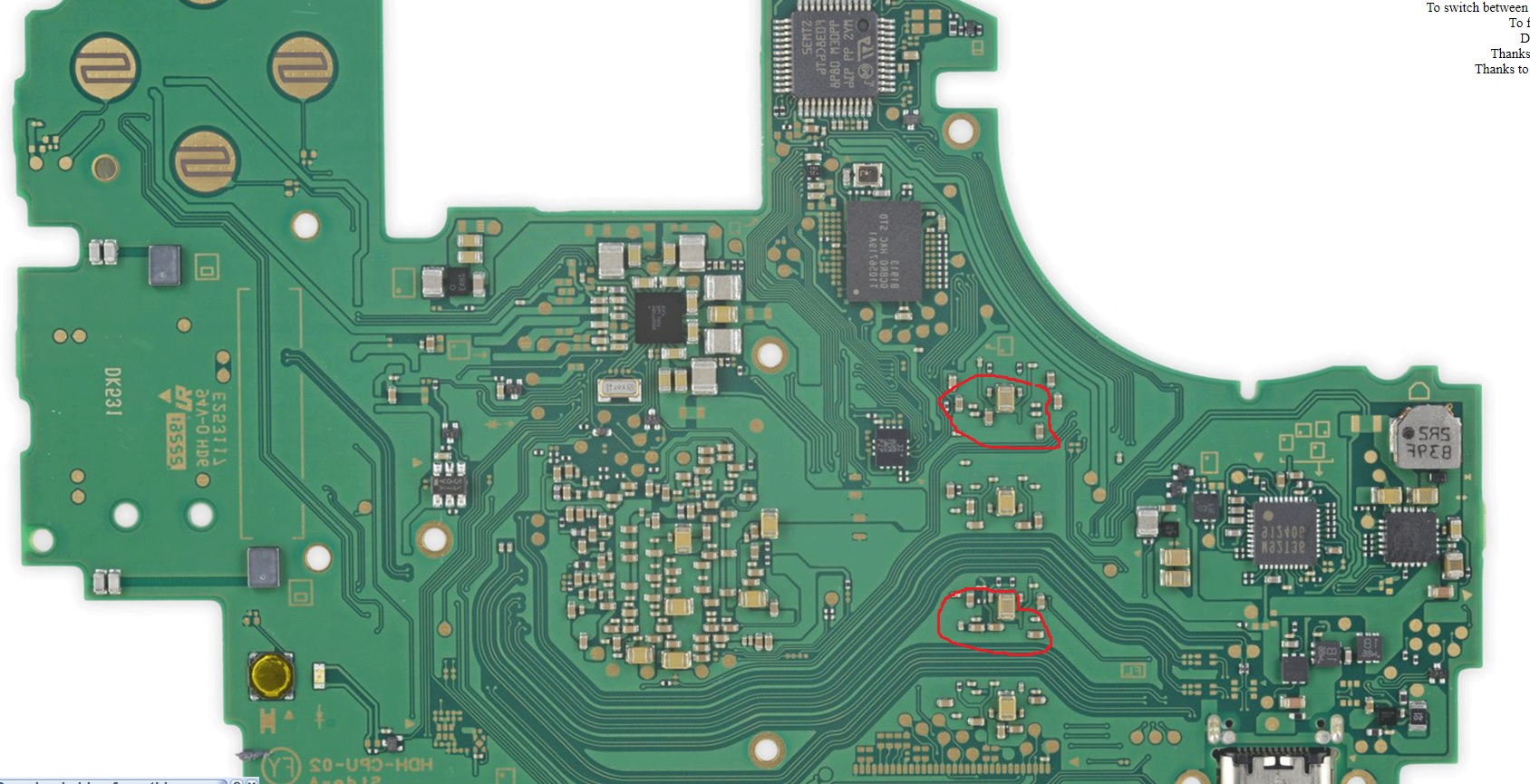
Have a switch llite that suddenly not powering on, plugged it in usb voltmeter, shows its charging @43amps… but no display, no baacklight. no sound,. so tried to test component around the board, no short found around m9, bq, area aat the back, fuse good. but i see low resistance reading on 2 large caps at the back of the board.(highlighted in red) and wanted to check if anybody knows what components these capacitor connected to that maybe causing the short.? TIA
As far as I know from my experince, they are connected to the SOC / CPU and normally means the board is Not fixable.
The 0,4x A also indicates a Shorted CPU.
Of course you can remove both caps and See if the short is still present.
These caps are on a ram rail afair and normally read a low resistance relative to ground
0.4A braindead isn’t normally “CPU” related, could literally be anything
When I have a working switch, These caps arent Shorted.
The OP didn’t say they were shorted
He wrote:
“what components these capacitor connected to that maybe causing the short”
So and with low Reading i think He means These are shortet at least in ‘beep’ - mode
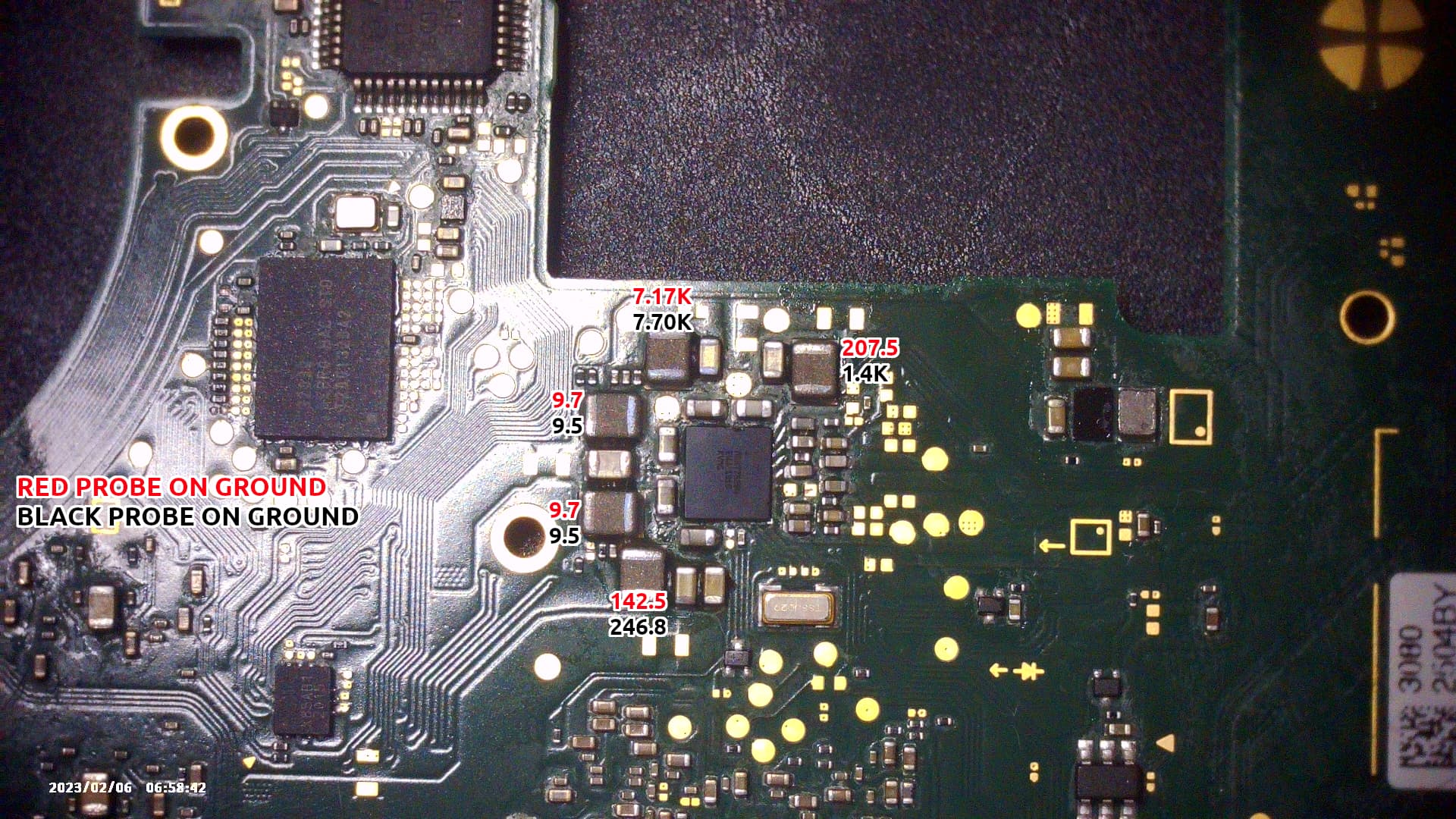
I’m sorry for resurrecting this thread, but I purchased a Switch Lite board on Ebay which is under the same condition – actually it was even worse, as two of those caps were beeping on my multimeter (I think they read 50.7Ohms each), so I replaced M92 chip and now I have it under the same condition as stated by OP. Those caps no longer beep, but now they read 257 Ohms, sometimes 259. As for the other two, they read 1.097 Ohms.
@Severence since those caps could be related to anything, where would you start checking for shorts? Switch Lite displays nothing, no sound, always stuck at .43A. Could this be related to power-management IC on the back of the board or even MAX77812 under the APU? Would you go as far as reflowing the APU or swapping it out for another one?
0.4A braindead can be a variety of things unfortunately ![]() best I can say is search the forum on this one and try to narrow things down otherwise I’d just be throwing everything including the kitchen sink at you as there can be so many different causes.
best I can say is search the forum on this one and try to narrow things down otherwise I’d just be throwing everything including the kitchen sink at you as there can be so many different causes.
The ones you thought you were having issues with were presumably relating to Ram, afair 257 ohms is about right on Lite. Maybe check your other primary rails incase you have other issues in this regard.
Hard to say. I wouldn’t reflow the SoC. You can’t change the SoC for another unfortunately unless you also have the matching EMMC which goes with your replacement. I also don’t know if the SoC is your problem either.Sorry this is just one of those pita faullts which is tricky to pin down.
Thanks for replying, @Severence .
I want to provide you with an update. Initially this board was outputting 0.43A and no display (as in dead, no backlight, no sound) and APU was dead cold.
After some googling and asking away, it turns out MAX77620 has something to do with that. Now that’s a 90-pin BGA chip, so it took me some time to get the job done. I finally did it but now the board draws 0A with no battery and 0.05A with the battery plugged in, which causes the APU to go super hot and I get backlight but a black screen. Fuse is fine as it beeps and diode mode value results are the same on both ends. Even with the system on battery only (no usb-c plugged in) the apu goes hot.
- I’ve checked for shorts around M92 and BQ, but found nothing;
** I’ve checked the middle pin from the battery connector (diode mode) to make sure MAX17050 is not to blame. Value is OK. And MAX17050 reports resistance in the Mega Ohms, so there’s nothing there I suppose.
– What could be causing the APU to go so hot when the battery is connected? I’m sure I didn’t mess with the soldering. Could it be a bad chip? Also, I think I should mention this: I’ve extracted it from a HDH-CPU-02 but I’m working on a HDH-CPU-10 model.
Please let me know if you need any test to be performed on the board.
Unfortunately these fault symptoms are not exclusive to this IC, so chances are this chip was fine all along ![]()
Would indicate the install was bad… I suppose it’s entirely possible the IC was bad or damaged prior or in the process. Unfortunately, given how important this IC is on the board and as you say because of the number of balls below, there is a high degree of probability the SoC is now damaged as a result based on your most recent symptoms ![]()
Shorted primary rail maybe? you could check the resistance to ground on your SYS rail, and then at all output inductors surrounding the PMIC
Resistance on 2r2 (black on ground): 1.433K
Resistance on 2r2 (red on ground): 207.5
As for inductor results:
So it’s all bad news then? That’s discouraging.
Well, is there a way I can at least get away with a working APU? Like, if I remove this damn chip and then what? Should it come back to outputting 0.43A, does that mean by any chance my APU didn’t end up fried because of that chip?
I think this is normal on Lite because of the diode… though i could be remembering wrong
your results at the PMIC, 1V8PDR seems a little low even for Lite board but it’s typical on some meters for this rail to be lower than expected soo we’ll give it a pass. Afaict your other readings are in the realm of ok. That being sai I do suspect your PMIC install is bad. Where did you get the IC from? did you reball it yourself with stencils and paste or was it preballed?
Depends. if for example you’ve inadvertantly bridged SYS (or similar) to some other low voltage I/O at the PMIC it would have killed the SoC instantly. If Changing the PMIC again resolves/returns your braindead 0.4A status then there is a chance the SoC is fine but given that it was burning hot following you changing the PMIC I wouldn’t hold out too much hope I’m afraid ![]()
I reballed it myself and used a 0.4mm stencil.
Well it actually gets hot when battery is plugged in.
By ‘killed’ do you mean a dead-cold APU that does nothing or a burning hot APU sucking up the battery like its life depended on it?
I see. Is 0.4mm in reference to pitch? as if it’s ball size that sounds a bit big to me… I’d have thought 0.35mm or lower
I’m really not sure if it matters but there is a different end letter designator on the PMIC on Lites/Mariko vs original rev boards, might be worth checking that. Are all the PMIC rails measuring good following prompt to boot. I suppose the one strange thing is your getting backlight.
I see. youo’d expect it to get warm but not hot - especially as I’m guessing your CPU/GPU is likely not even active at this stage. If (secondary) CPU and GPU were active then it would take several mins even without heatsink to go above 50C and thats entering OS etc
Burning hot
When placing the chip under a 0.3mm grid, it just didn’t look normal to me, so I was set at 0.4mm and I haven’t had mixed results, which was the case for 0.3mm.
OK, I think I’ve figured it out.
I have a contact of mine that does board repair all the time, so I had him send some spare boards to me and see if I could resurrect one of them. I picked the one that had most components unpopulated and started working on it, and had three other spare boards just in case.
Daughter board connector, and the neighboring capacitor & resistor, along with a fuse, M92, BQ, battery connector have all been soldered onto this board. And then I tried it and then the issue from this thread came up. Then I was told to give the PMIC a try and I did.
Only I didn’t pay too much attention to the fact that I was working on a HDH-CPU-10 model and my spares were all from HDH-CPU-02. This past Saturday I was like “Oh well it shouldn’t matter really because often times you see people interchanging components from regular switch to the lite, so why bother?”
And now we know why.
Apparently, Switch Lite boards are tied to restrict components.
Meaning a HDH-CPU-02 board will work fine with MAX77620H;
But if you’re working on a HDH-CPU-10, you should go with MAX77620A. I could be wrong so prior to typing this answer, I carefully removed the PMIC chip from the board and found no shorted pads. Not that that means something but… anyway, connected a battery to the now-unpopulated PMIC board and it’s back to the .43A ‘braindead’ state.
That’s probably because the PMIC chip was working as it should but on the wrong, ‘unsupported’ board because it was designed for a newer revision. This could be all but a simple theory I’m coming up with, but I’m out of MAX77620A/MAX77620 or whatever version that’s compatible with HDH-CPU-10.
I’m sorry for the long reply.
I’d guess from your description that this is referencing pitch as opposed to hole/ball size - every stencil is different in this regard. to confirm you can just see if a 0.4mm preformed ball fits or 0.35 or 0.3 etc
Right, this is what i was reffering to above with the end letter designator. Lites/Mariko have a different end letter on their respective PMIC compared to original erista. Whether or not this makes a difference I don’t remember but I’m 95% sure the pinout is identical between the two despite the markings, so using one in place of the other shouldn’t have caused high heat at the SoC to the best of my knowledge but I haven’t confirmed it. As your now getting approx 0.4A following the PMIC removal it does suggest a bad IC or bad install with 99% probability ![]() the SoC is still fine bud
the SoC is still fine bud
I think I had one case on Mariko with orange screen, swapped the PMIC from a regular Erista board onto the Mariko one, symptoms remained the same, no high heat at the SoC etc. though this is the reverse of your situation.
Oh I see. Have you ever replaced a PMIC on the HDH-CPU-10 (Switch Lite board) with a MAX77620H? I’d love your feedback, that’d be awesome.
I don’t think so but Mariko boards are fundamentally the same as Lites (hardware/component wise) so it’d be similar. but it’s worth bearing in mind, that as the fault symptoms on my Mariko were an OSOD, it might have not exhibited something which might oridinarily be seen or not seen
I’m still struggling with this 90-pin bga chip, NGL.
Well I believe I saw thecoder running into a similar issue, which was related to the wifi/BT card. Nonetheless I believe you had your reasons to replace the PMIC.
See, the PMIC is a rectangular chip with a 9x10 pin configuration. If I use a 0.30mm or 0.35mm, I always count more cutouts than solder spots. 0.40mm always seems to be spot-on.
Say that I need to move an apu+hynix nand from HDH-CPU-10 over to a HDH-CPU-02 which had an apu+samsung nand. Would that work?
Yeah unrelated
Yeah, afaict you mean the holes don’t align with the IC’s pads when using a “0.35mm” marked stencil or lower. What I’m saying is the markings on a lot of stencils don’t relate to ball/hole size but rather pitch (if the pitch is wrong it won’t align). icbw but i really can’t see the ball size on the PMIC being 0.4 but then again, I’ve never checked this with preformed balls ![]()
Yes it should work fine but if your having troubles with the PMIC then you’ll have more with the SoC as it’s incredibly sensitive to heat and I don’t care what anybody says, you can’t reliably and repeatedly reball these SoC’s with stencils and paste it’s just too big… atleast not without other more advanced equipment alongside such as a hot plate or IR heat station (which takes us back to the high heat sensitivity of the IC) - so you’d have to get a specific jig, dedicated stencil and preformed balls and even then it takes a lot of practice ![]() so I’d suggest against doing this.
so I’d suggest against doing this.