Nay, this board doesn´t have this IC, nor the one on the bottom. I’ve check continuity from USB to the data testpads and testpads diode readings and everything is good.
Now you understand why I’m completely lost on this one lol
Nay, this board doesn´t have this IC, nor the one on the bottom. I’ve check continuity from USB to the data testpads and testpads diode readings and everything is good.
Now you understand why I’m completely lost on this one lol
Hmm.
This seems to be one of those cases where the parts involved are working as intended¹ (BQ & M92, if you look at them individually), but due to some reason² there is an i2c-comm fault³ at play.
1 <> according to your statement, another working Switch has one of BQ’s caps at 1.1V;
2 <> The reason is unknown. I have a suspicion and it’s a 9-pin BGA chip that one of BQ’s caps talks to: ALJ 922 and this chip is present on the Switch Lite, but you gotta find it on your regular Switch board. There’s a cap sitting right next to it, and if it’s shorted, it could indicate that chip needs a replacement.
3 <> Lack-of-communication between M92 and BQ, which could be caused either by a faulty chip, a partial short, a missing or open resistor or a busted i2c track.
Believe me,I’m trying to filter out as many variables as possible, and those are the ones you’re dealing with right now.
Many thanks for your insights.
I’m just wondering what’s the bare minimum for the charging system to work.
So as I mentioned, I tried injecting 5V straight into the BQ and it still draws 0 current and refuses to charge the battery. This would hint that, while some comm problem between BQ and the rest of the board may exist, it should not be the reason for the BQ to not charge while injecting voltage (unless BQ actually needs this comms to start charging)
So my question is, asumming we inject voltage at Vbus, what else has to be working for the BQ to charge?
PS: rn I’m out of home so can’t really test anything until tomorrow
I wasn’t going to mention it, but since you’re asking…
BQ is directly related to the USB-C port. Plus, when it comes to CHARGING, there’s a very low prob that your PI3 could also have something to do with the fact that it isn’t charging. Now, I don’t like playing theories when it comes to desoldering or soldering stuff onto the board, but because you really don’t have anywhere else to look, have a go at those two remaining components I mentioned. Who knows…
… but if that doesn’t work (and it most likely won’t TTYTT), you need to face the fact there’s a short on the board. Maybe not an evident short (as in the most common spots), but who knows maybe it’s on the audio IC (or its satellite components), maybe it’s somewhere you least expect it. It’s sit-down-and-start-probing-everything time if you aren’t ready to let go of this board just yet.
Alternatively, if you know very little (or nothing at all) about the battery that you’re using to test the board with, you might wanna consider another battery. Yes, seriously.
This is the nintendo Switch after all, and pretty much anything could be the source of a nightmare, down to the battery.
Well I’ll test everything i can. Thanks
Battery is good as it charges on other boards
Found this:
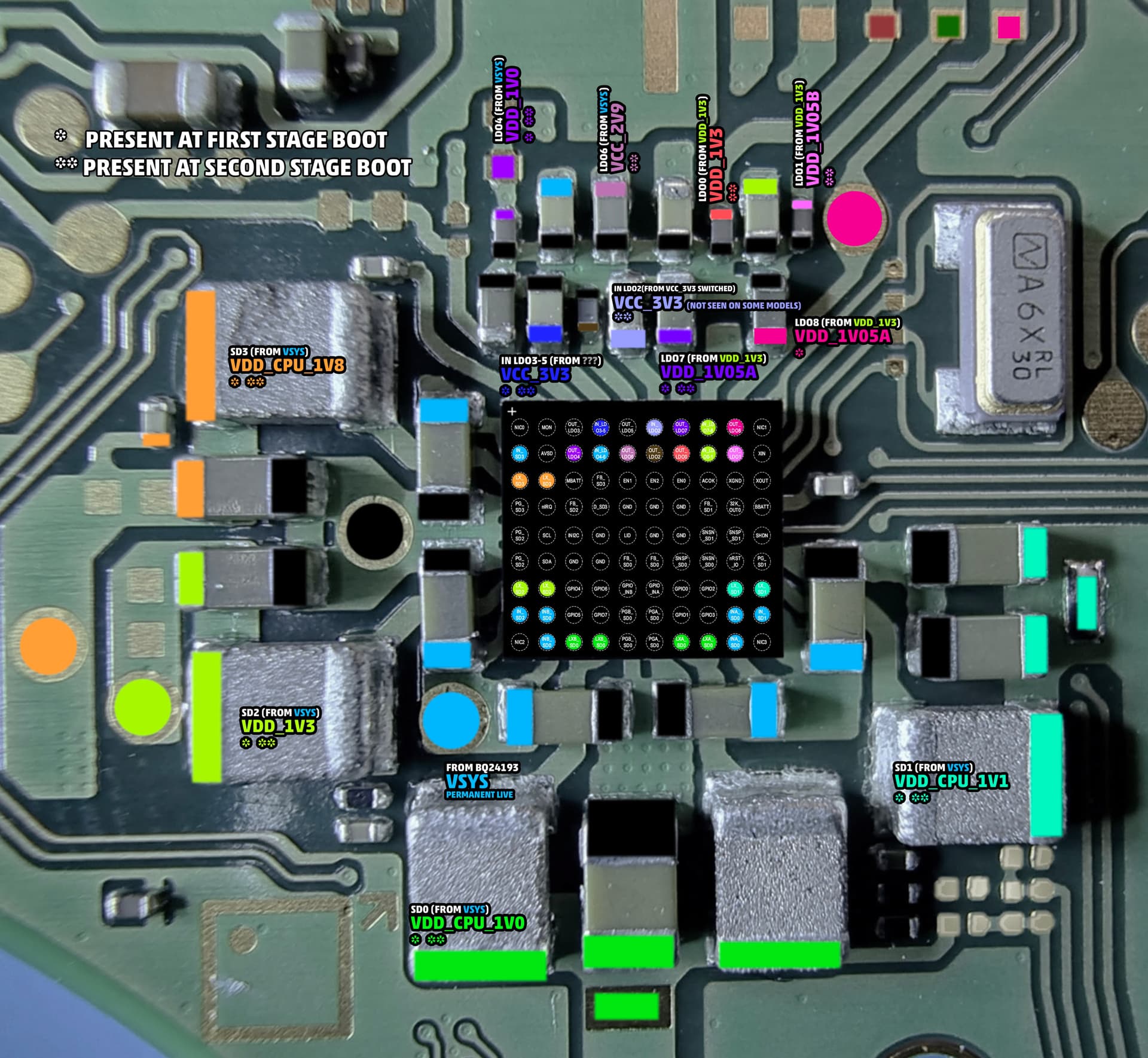
BQ - pin #13 - Power Good (Active low) - Goes to MAX 77620A, which is a Power Management IC (PMIC).
When the board is powered, measure that pin in Voltage mode and if you see low voltage, that means BQ is broadcasting “power good” to MAX 77620A.
After you confirm that, your board is stuck at first stage boot. Move to MAX77620 and check the voltages marked with a single asterisk (*) from this picture.
Update on this one.
I tought I had it fixed and now I’m back to square one lol
So i inspected closelly the BQ chip and noticed some pads were not properly soldered so I reflowed the IC, plugged the charger and boom, it was charging. At this point I thought it was fixed but when the console was on, it refused to charge again. I thought, well, has to be some other weak solder joint on the chip so I reflow it again and now I’m back to were I began. Power wont get to BQ because M92 wont turn on the mosfets so It might be some communication issues between BQ and M92. How can I test this?
Is there some reference values for each of the BQ pads with the IC out so I can test every single pad of it?
Unless you’re pushing overvoltage, it makes no sense for M92 to be blocking power from coming into the board.
As for the MOSFETs, make sure they aren’t shorted.
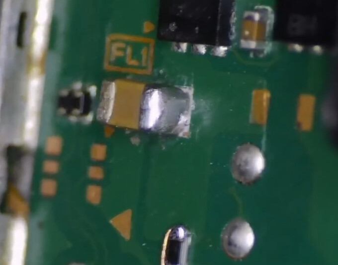
Make sure this cap is soldered to the board (sitting between the first MOSFET and the fuse):
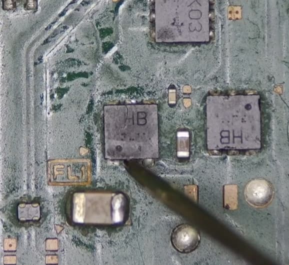
Now, if you get a continuous beep on this pin:
And if the cap long-beeps on both ends,remove it and test its pads.
If the short’s still there, replace M92.
Else, replace the cap.
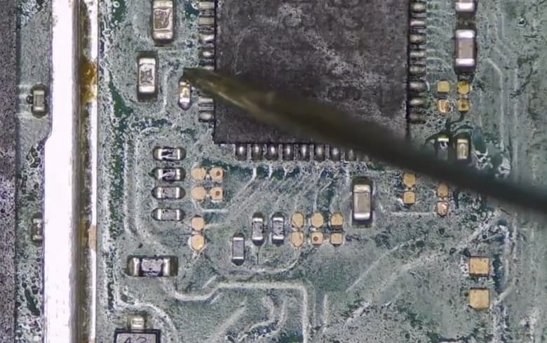
Next, scroll up and refer to post #5, make sure that resistor hasn’t gone open.
When you test the resistor by probing the ends, your multimeter will struggle to give you a reading, switching from KOhms to MOhms, back and forth. That means the resistor is working as it should.
More updates lol
So since I was getting no voltage on the mosfets I just swapped them again. Placed new mosfets and I was getting 5V back into BQ. Reflow BQ and console was charging again. Even with the console on.
Out of nowhere, the console stops taking charge for no reason again (I think it happened when I tried to dock it). Check mosfets, again,no power into BQ.
So, or is something that is messing with the mosfets or is some broken inside via which only makes contact when the board is way to heated up.
I swapped P13 just in case it was that messing with the mosfets but doesn´t look like it