Im dealing with a Switch that boots perfectly fine with a good working battery but refuses to charge. Gets 0 amps when plugged.
Checked for shorts on everything related to the charging circuit and eveything looks fine. Swapped M92 for a known working one, same for BQ, Fuel gauge data looks Ok on Hekate so didn´t change it.
What I found: Low Vbus voltage getting to BQ. Mosfet’s gates voltages coming out of M92 looks too low. First mosfet gate gets 3.5V and outputs 270mV. Second mosfet gate gets around 270mv too so BQ gets no power when powered over the USB but it does when powered from the battery.
Are you positive the fuse is alright?
If so, then make sure the charging current is reaching BQ.
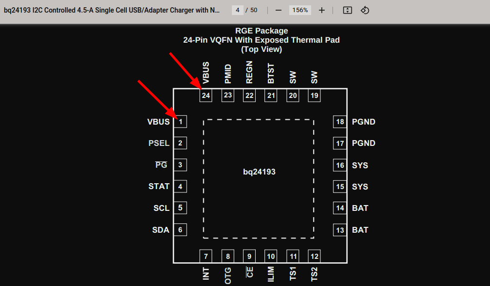
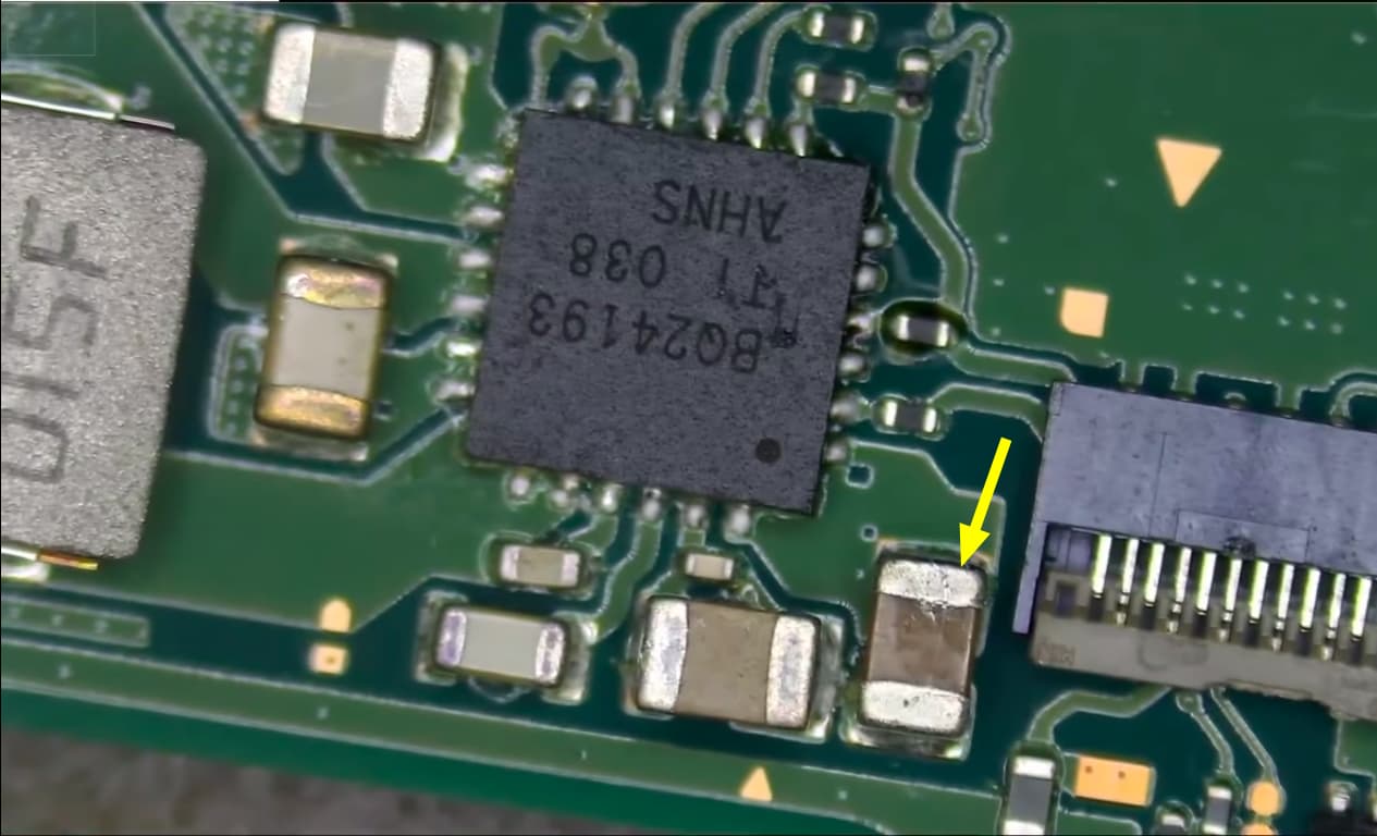
To do that, check the voltage on those two legs, they’re for Charger Input Voltage (VBUS)
After that, check pins #19 & 20 to make sure the BQ chip is having no problems when talking to (Switching) the inductor.
Finally, have a look at pin #23 (Voltage reading) and COMPARE its value to #1 and #24. If they’re different, your BQ chip is faulty.
Fuse is good
M92 I assume is good (As it turns on the FETs and negotiates 15V)
BQ does get Vbus
Pins #19 & #20 must have connection to the coil as I can measure Vbat on the coil when battery is plugged
Voltage on #23 is some mV lower than #1 & #24 but not sure if enough to call it a bad BQ. Im measuring 4.99V on #1 and 4.97V on #23
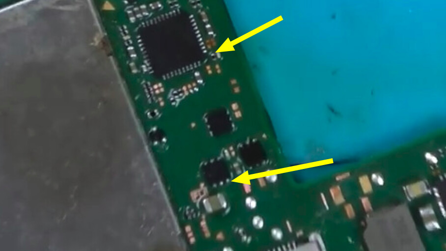
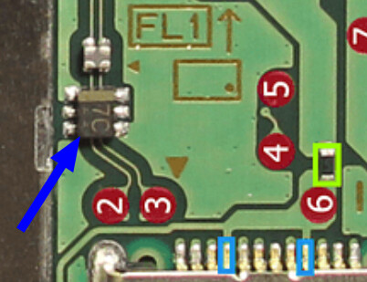
Alright so if I’m getting this correctly, so far your Switch won’t charge the battery when connected to AC, despite swapping MOSFETs. What I would do next is, to make sure M92 actually DOES speak to the MOSFETs. Have your meter in diode mode, no battery connected, disconnect USB-C cable. Have one of the probes touching the TOP of this resistor and the other one to the gate of this MOSFET (check pic)
Additionally, have you checked if the USB-C port is firmly in place?
Give it a little nudge and make sure all legs are making a solid contact with the pads.
Yes, it takes 0.00 A.
Also checked the USB-C port in diode mode with a breakout board to check every pin individually and I get the correct reading on all of them.
I suspect your Nintendo Switch has no usbd (USB detect), therefore no VCONN_IN (5V), but I could be wrong. You also mentioned your dock flashes rapidly when the Switch is connected, so have you tested the big cap next to PI3USB? What about the filters, does your meter beep when you cross-test them? (it’s not supposed to).
I find your case very interesting because you mentioned that power gets to BQ, yet there’s no current being drawn. Weird.
Anyway, when you attempt to charge the Switch, touch the battery terminals (from the battery connector) with your probe in Voltage mode. If you see the voltage measurement going down, you’ve got a short.
Check the caps around M92. Does anyone of them beep when you probe them on both ends of the cap? What about the ones around BQ?
Oh and before I forget, we should be certain VCONN_IN is NOT missing for M92T36.
So have your meter in Voltage DC, probe pin #36 from M92, Switch needs to be on.
If you get 0V, that means nothing is supplying power to M92’s internal power supply.
P13 looks fine, tho I didn´t try to swap it. No shorts around it, all pins diode readings looks ok and filter are good (continuity on the same line, open on cross)
Battery has no current draw.
Caps around BQ and M92 looks ok, no shorts. Coil isn´t shorted either.
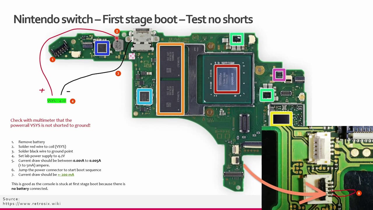
Also, I forgot to mention. I did both the power from bench and charging from bench test:
Powering the console from bench (Injecting VSys at coil) works fine and console turns on (With the bypass resistor) but charging from bench (Injecting vsys on BQ cap) still gives 0.00 A current draw so I’m eager to believe there is something wrong with the BQ or anything around it.
Pin #36 it’s a bit weird. With usb and console off I get 4.5V, no matter if battery is connected or not. But if I turn on the console it takes like 5-6 seconds to jump to 5.5V
Now, considering you’ve swapped the MOSFETs, M92 an BQ, might as well go the extra mile and do the same to PI3, USB-C port and Coil, as those are components that can read OK but still be faulty sometimes.
Console boots perfectly fine so I highly doubt it’s a SoC problem. Also in my case injecting voltage into the BQ gets no current draw so no short on that line.
No offense intended but NRF here stated that a 1.1V drop here is wrong and I’m quite sure is fine on this board model (So he was chasing the wrong thing). You can see in this thread:
www.tronicsfixforum[dot]com/t/reading-on-bq-chip-off/3939/10
The same thing getting asked for this board and working consoles do have a 1.1V drop here because it’s just build different.
Also checked MAX IC just in case and everything seems to be correct.
Yeah, I’ll probably go with that eventually but wanted to try to actually pinpoint the problem so I dont have to risk a working board swapping working things.