Ive checked that it makes perfect contact and that shouldnt be the reason it doesnt turn on right?
Not sure and I don’t want to give you bad advice on the basis of sheer memory, but I would try to rework m92 just in case the solder has bridged some stuff down there. I’ve had to rework it a few times before I got mine right, wait until the solder in the middle square becomes liquid
I will definetly try that but if theres not enough volt on the input line it most likely isnt the chip itself or am I wrong? (Im not that experienced sorry)
I’m sorry I understood there were 5v input even on the old m92?
Yeah, I totally forgot the input worked before I replaced it. Well it isnt 5V anymore
Sounds like a faulty chip or a suboptimal soldering job (done both multiple times…) Can you edit in a picture where and that measurements are you taking?
Yes give me a minute
Here is a M92-like chip datasheet from the same company, it should be useful if you want to dig dip into pin specific measurements (don’t ask me to interpret it though as it’s well beyond my knowledge  )
)
https ://d1d2qsbl8m0m72. cloudfront.n et/en/products/databook/datasheet/ic/interface/usb_pd/bm92a30mwv-e.pdf
ht tps :// imgur. com /a / x8gJuH7
Can you measure voltage on pins 4 and 6 on the north side of this picture (with charger on)? I will also highlight some sketchy joints I am seeing. I’m sure most of these are just flux reflexes but double check them all (some definitely do look like there’s too much solder and/or they need to be readjusted)
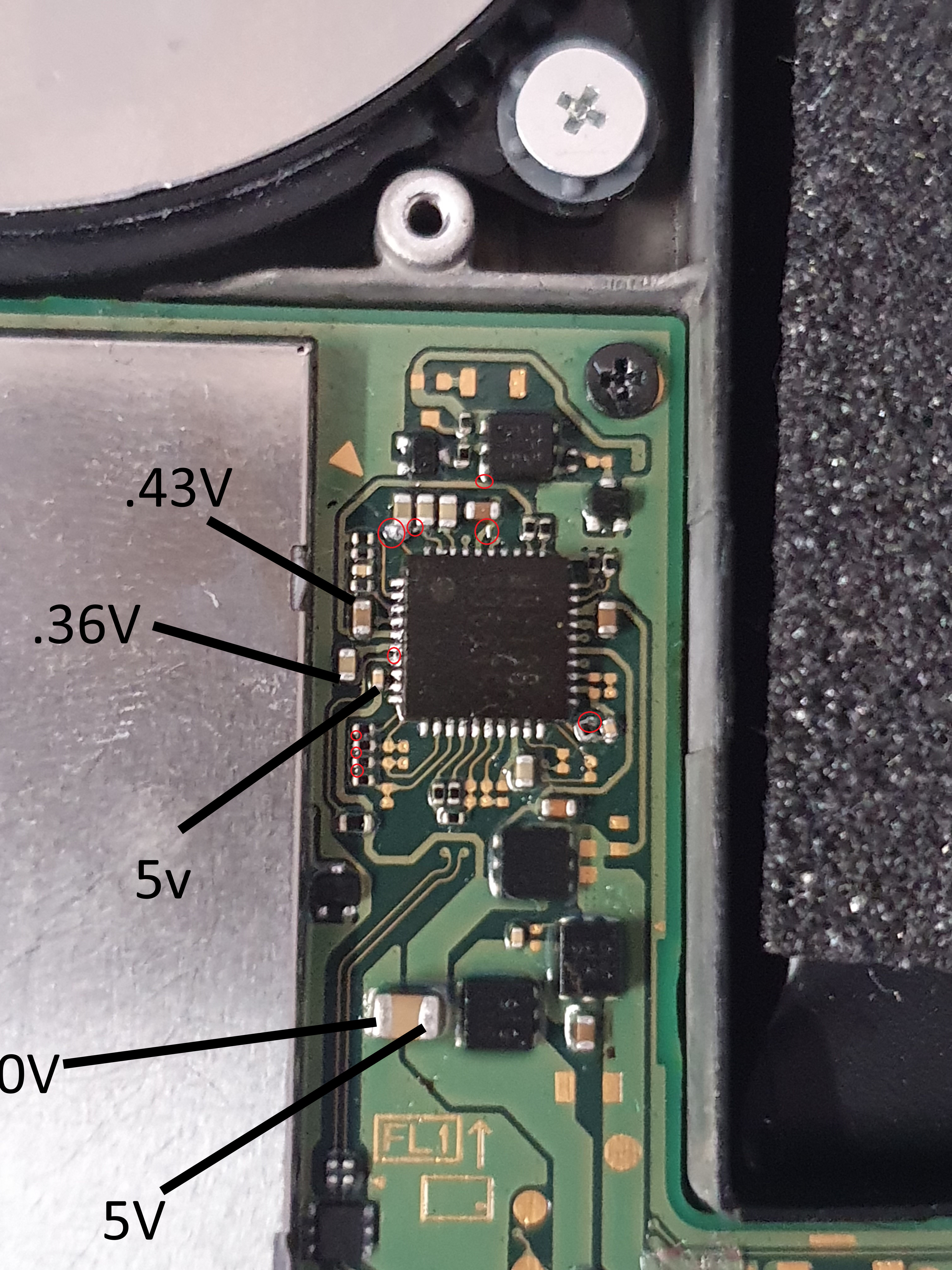
Pin 4 is .43 like on the cap and pin 6 is .4 I also saw that reflection on the photo between those 2 pins but its only a reflection. On the row of 3 caps on the bottom side theres no connection (measured) but the top has a connection (But I dont know wether that is normal). The two really small caps to the bottom right make contact with their dedicated pads.
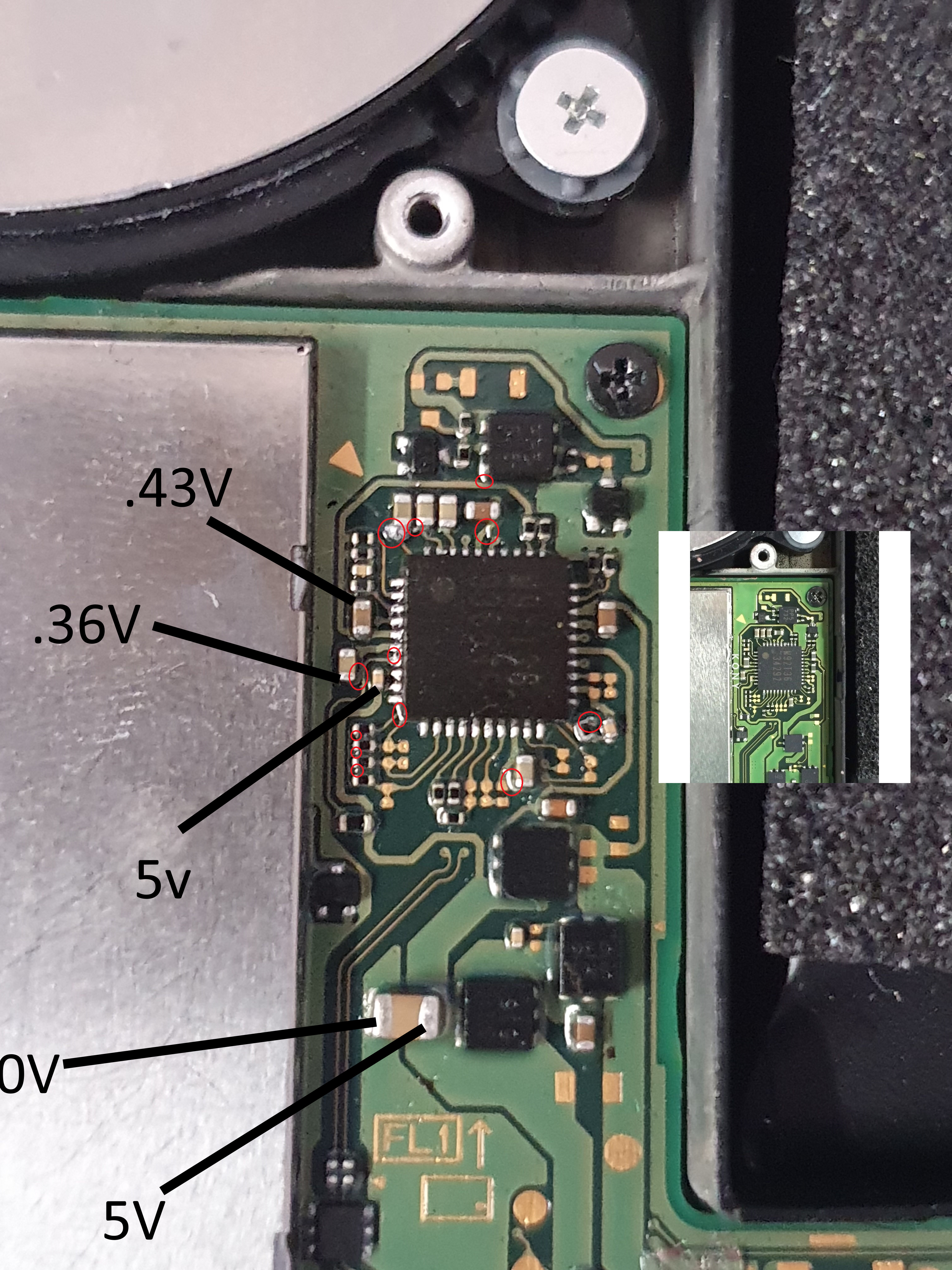
Try to clean that solder thing on pin 6, I updated the picture with a reference on how a m92 should look like
I’ll start cleaning it right away. I will get back to you when im finished
I cleaned it up. Still no signs of life (would’ve been really great :D) I dont think this switch is really fixable. Do you have any more ideas?
Pin 4 and 6 north side should be the input from the usb C port CC1 and CC2 that enable fast charging. I don’t recall what voltages they’re supposed to be. You should look in that direction (gbatemp forum, google and the datasheet I gave you should help you find the answer). If those voltages are high enough and you’ve cleaned every joint, then I’d rework m92 completely. If the voltages are too low (again I don’t remember how much they should be) maybe it depends on PI3, not sure though.
If I find that info I’ll reply to this post, right now I’m deep into work and I can’t find it immediately, sorry about that.
Don’t worry. But maybe you know this one on the fly: I’ve read that the switch boots up into handheld mode even without p13. Ive removed that and tried turning it on but it still didn’t work. So I’ll rule out this chip
I’ve heard about that rumor too, but if you have no reason to believe your PI3 is faulty I would keep it on since it could influence the voltages reading compared to “healthy” levels and you wouldn’t know it.