Hi , I put a chip in a working v2. After turning on, the chip turns green ( good connections) but the switch display screen is showing the first stage of powering up (from black to dark grey ) , No nintendo logo though and after 15 s it powers down. After removing the chip same thing.
Connecting to the dock gives a good display on TV but still nothing on the screen of the switch.
With the advise of sthetix i replaced the ic 8316. Didnt help.
Any ideas frds ?
If the console is on and working in the dock, and you have backlight but no display in handheld, I would always start by inspecting the LCD connector.
Will have a look ag thanks
Replaced the lcd connector , didnt help. Still get backlight on the screen but tv dock displaying ok on tv……
i checked all ok there
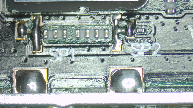
I’m not really sure at that point. If you have a known good screen you can test with, I would try that. Some board also have little filter things on the signal lines also (of the ones I have here, only one has them), I am not sure how you test them, but you could take a look at those and compare with a known good board… otherwise I would start to suspect an issue at the SoC, but maybe someone else has more ideas as to what might cause a no-display issue.
I suspect something went wrong when i soldered the chip ribbon to the capacitors around the cpu
!
I actually have a Switch is doing something similar to Mirivedan’s Switch. My Switch when plugged into the 5v charger, will display with backlight the battery charge symbol on upper left hand corner. It will then flash the Nintendo logo for booting and then the screen goes dark, no backlight, no picture. However the Switch is on since I can hear the menu being accessed when I touch the digitizer.
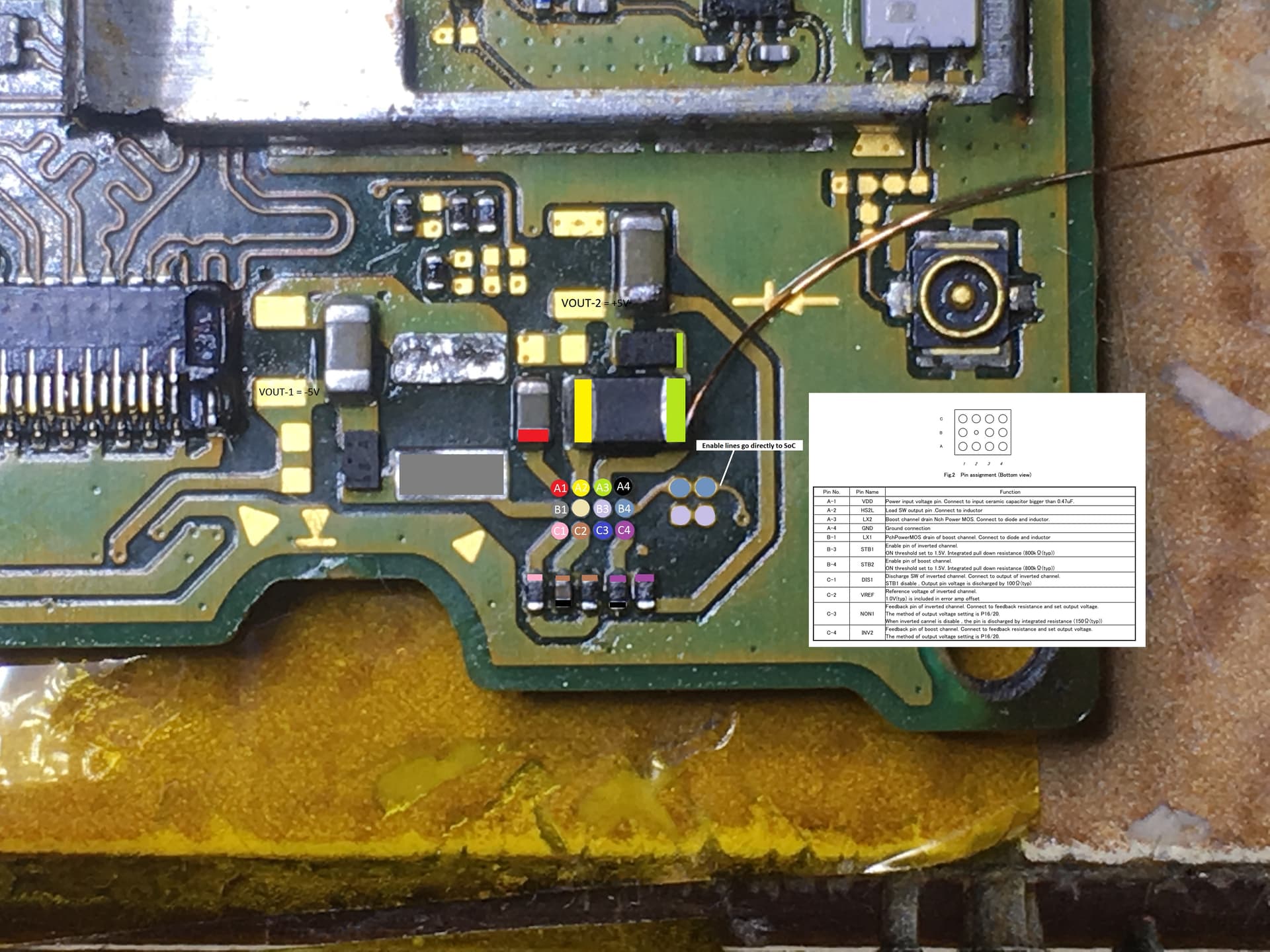
I also measured VOUT1 and VOUT2 and both are producing -5v and +5v respectively. My 3V3PDR rail was initially measuring a very low diode reading of 170 (measured at cap next to M92 and at respective big and small caps around P13), much lower than other Switches I have and per Calvin’s diagram. I then pulled M92 and P13 and the low diode reading didn’t change. I don’t have reballing stencils (they are on order) so didn’t pull ENXX, WIFI or main PMIC as I understood all these lines are connected to 3V3PDR.
I did notice some corrosion on my LCD connector, so I swapped that. Once that was swapped my diode readings on 3V3PDR changed from 170 to 330, still lower than other working Switches and Calvin’s charts but thought I was making progress. But alas the LCD continues to not function in handheld mode. I tested the USB C port with a breakout board and confirmed continuity to respective board measuring points. The Switch works in dock mode, displaying picture as well.
I’m beginning to suspect its the SoC since this Switch has gone through some water damage and for whatever reason the SoC once passed the boot process (LCD and backlight work for displaying battery charge symbol and Nintendo logo) won’t enable the LCD. Does anyone know, other than the 1.8V enable pins on 8316, if there are any other enable points needed for LCD to display?
These are the points i soldered before the switch went faulty